
Uniform cutting device for tipping paper

A tipping paper and cutting technology, which is applied in metal processing, mechanical equipment, springs/shock absorbers, etc., can solve the problem that the cutting device does not have the detection function, cannot cut the product size verification, and does not have the function of dust removal and sterilization To achieve the effect of realizing automatic continuous cutting operation, ensuring dust-free conditions, and improving cutting accuracy

Inactive Publication Date: 2021-05-11
驻马店黄金叶实业有限责任公司
View PDF9 Cites 0 Cited by
  • Summary
  • Abstract
  • Description
  • Claims
  • Application Information

AI Technical Summary

Problems solved by technology

[0008] Aiming at the deficiencies of the prior art, the present invention provides a uniform cutting device for tipping paper, which can solve the problem that the existing uniform cutting device for tipping paper does not have the function of dust removal and sterilization, and debris is easy to accumulate at the incision of the tipping paper and bacteria, causing the problem of poor hygienic quality of the tipping paper after cutting and the existing cutting device does not have the detection function, it is impossible to check whether the size of the cut product is qualified, and the quality of the finished product cannot be guaranteed; this device has passed the Set up a small vacuum cleaner to absorb and collect the debris at the incision to ensure the dust-free conditions of the cut products. At the same time, alcohol is installed at the bottom of the incision, and through the evaporation of alcohol, the incision is sterilized in an environment with volatile alcohol. , so that the hygienic quality of tipping paper cutting products is guaranteed

Method used


Image

  • Uniform cutting device for tipping paper
  • Uniform cutting device for tipping paper
  • Uniform cutting device for tipping paper

Examples


Embodiment Construction

[0028] The following will clearly and completely describe the technical solutions in the embodiments of the present invention with reference to the accompanying drawings in the embodiments of the present invention. Obviously, the described embodiments are only some, not all, embodiments of the present invention. Based on the embodiments of the present invention, all other embodiments obtained by persons of ordinary skill in the art without making creative efforts belong to the protection scope of the present invention.

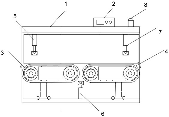
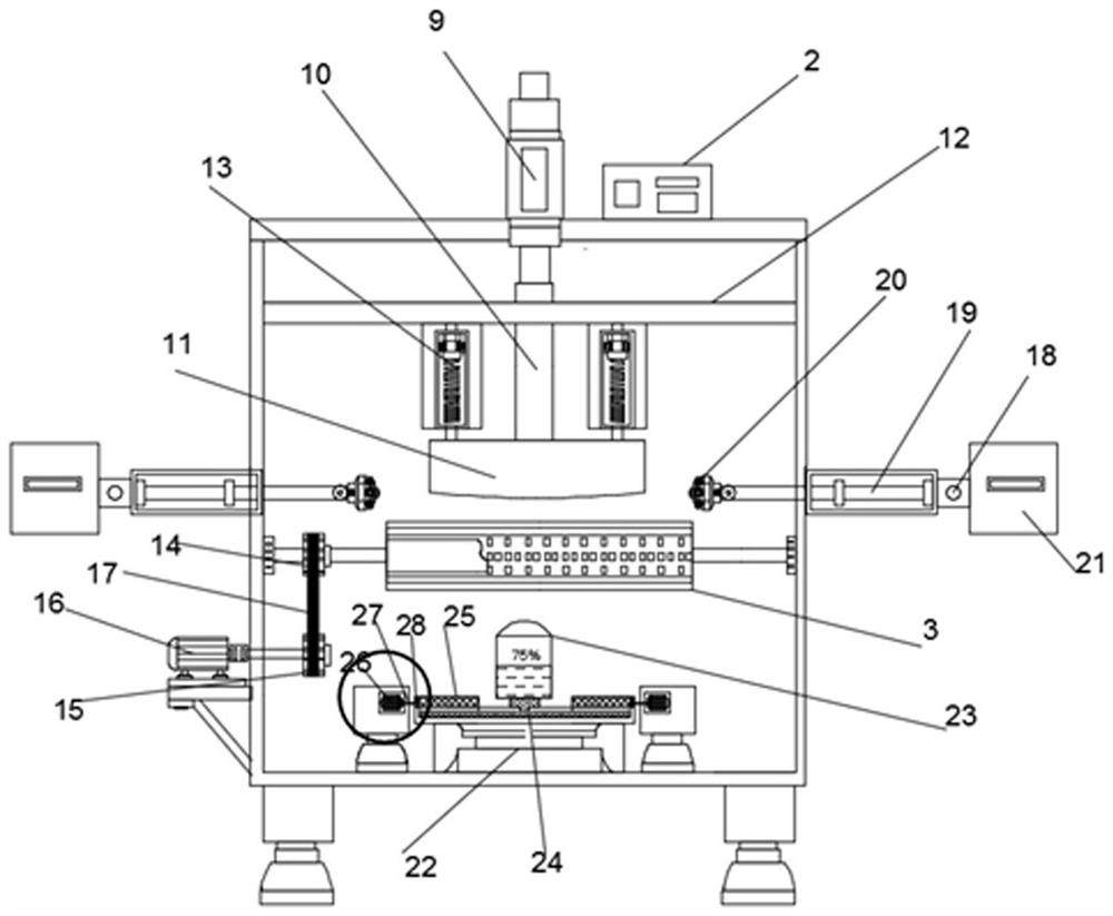
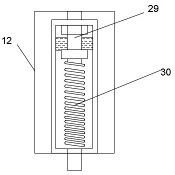
[0029] see Figure 1-4, a tipping paper uniform cutting device, comprising a device main body 1, a controller 2 is arranged on the top of the device main body 1, a first conveyor belt 3 is arranged inside the device main body 1, and a second conveyor belt is arranged on one side of the first conveyor belt 3 Belt 4, a cutting mechanism 5 is arranged on the top of the first conveyor belt 3, a sterilization mechanism 6 is arranged between the first conveyor belt ...


PUM


Abstract

The invention relates to the technical field of paper cutting devices, and discloses a uniform cutting device for tipping paper. The uniform cutting device comprises a device body, a controller is arranged at the top of the device body, a first conveying belt is arranged in the device body, a second conveying belt is arranged on one side of the first conveying belt, a cutting mechanism is arranged at the top of the first conveying belt, a sterilization mechanism is arranged between the first conveying belt and the second conveying belt, an infrared detector is arranged at the top of the second conveying belt, a buzzer alarm is arranged on one side of the controller, an air cylinder is arranged at the top of the cutting mechanism, and a pneumatic lifting rod is arranged at the bottom of the air cylinder. According to the uniform cutting device for the tipping paper, the dust-free condition of cut products is guaranteed through arrangement of a small dust collector, meanwhile, alcohol is arranged at the bottom of a cutting opening, and the sanitary quality of the tipping paper cut products is guaranteed through alcohol evaporation. Meanwhile, an infrared sensor is arranged to intelligently detect the size of the cut products, and the quality of the cut finished products is effectively improved.

Description

technical field [0001] The invention relates to the technical field of paper cutting devices, in particular to a uniform cutting device for tipping paper. Background technique [0002] At present, cigarette packaging is an important part of cigarette production and the last process in the entire production process. In the whole process of cigarette production, circulation and consumption, the quality of packaging materials plays an important role in maintaining the quality of cigarette products, promoting sales and guiding consumption. Compared with other commodities, the requirements for cigarette packaging materials have certain particularities, such as: no peculiar smell, non-toxic and harmless to the human body, and certain moisture-proof and insulating properties. Aluminum foil paper for cigarettes is composed of aluminum foil and inner lining paper through an adhesive. Its function is mainly to wrap the cigarettes in the cigarette box, maintain the storage environment...

Claims


Application Information

Patent Timeline
Patent Type & Authority Applications(China)
IPC IPC(8): B26D1/08B26D5/12B26D7/08B26D7/18A61L2/18B07C5/10F16F15/02F16F15/06
CPCB26D1/085B26D5/12B26D7/08B26D7/088B26D7/1863A61L2/18B07C5/10F16F15/022F16F15/06
Inventor 崔献锦于芊赵书高
Owner 驻马店黄金叶实业有限责任公司
Learn More