
A blast furnace blowing device

A technology of injection device and blast furnace, applied in blast furnace, blast furnace details, blast furnace parts and other directions, can solve the problems of reducing the utilization rate of waste plastics, blockage of feeding pipes, and difficult to clean up feeding pipes, so as to improve the effect and improve the utilization rate. rate, the effect of strengthening the detachment effect

Active Publication Date: 2022-07-22
JINAN YISIDA AUTOMATION ENG
View PDF0 Cites 0 Cited by
  • Summary
  • Abstract
  • Description
  • Claims
  • Application Information

AI Technical Summary

Problems solved by technology

[0005] Aiming at the deficiencies of the prior art, the present invention provides a blast furnace injection device, which solves the problem of recycling waste plastics. Since the mixture of plastic and heavy oil is transported in the delivery pipe, some plastic particles will be deposited at the bottom of the delivery pipe. , Some impurities in the heavy oil will also precipitate and mix with plastic particles, deposit and agglomerate, and accumulate in the delivery pipe. It is difficult to clean the inside of the delivery pipe. It will cause blockage, and at the same time, the compounds in some plastic particles will be deposited under the base if they are not completely decomposed, reducing the utilization rate of waste plastics

Method used


Image

  • A blast furnace blowing device
  • A blast furnace blowing device
  • A blast furnace blowing device

Examples


Embodiment

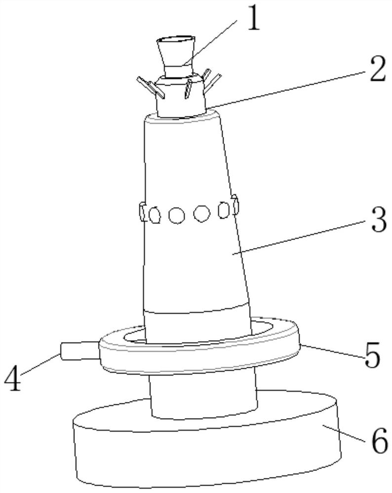
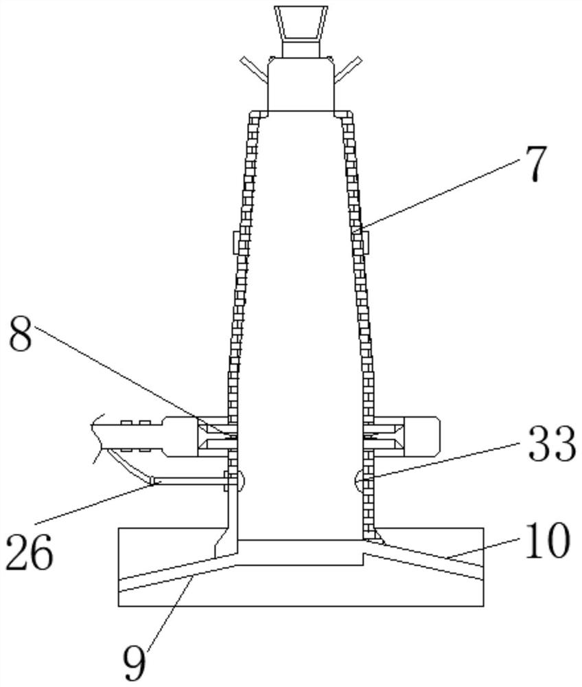
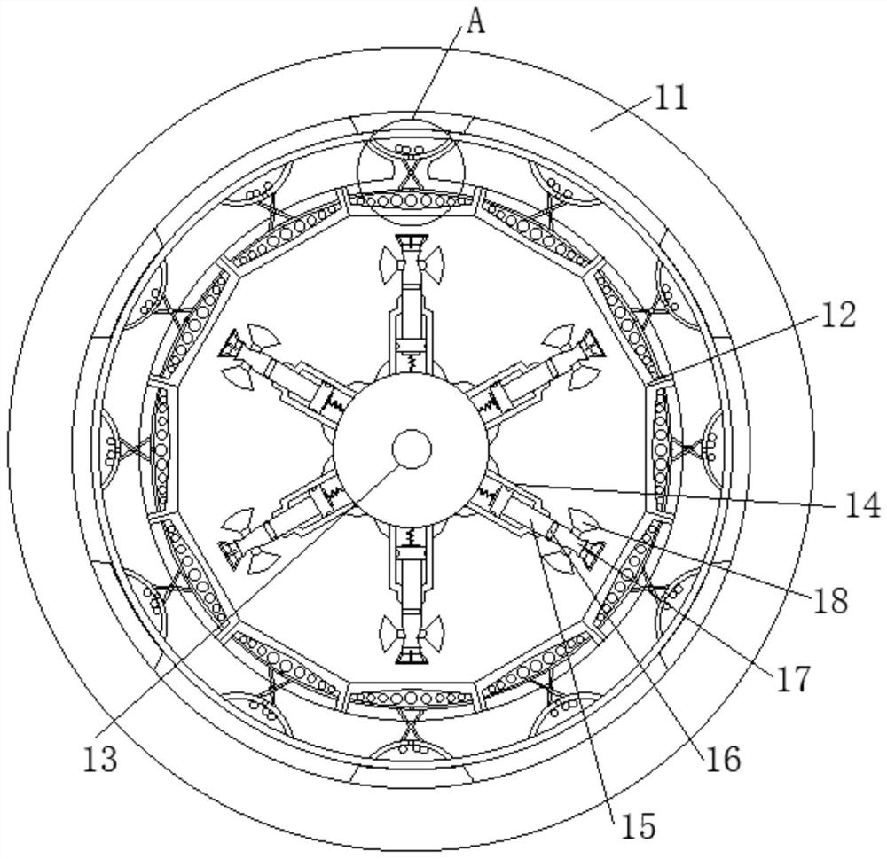
[0027] like Figure 1-7As shown, the embodiment of the present invention provides a blast furnace blowing device, including a feeding hopper 1, a filter cylinder 2, an outer layer 3, a feeding pipe 4, a fixed plate 5 and a base 6, and the filter cylinder 2 is arranged at one end of the outer layer 3. The outer wall, the feeding hopper 1 is arranged above the filter cylinder 2, the feeding hopper 1 is communicated with the filter cylinder 2, the inner wall of the outer layer 3 is provided with fire-resistant and heat-resistant bricks 7, and the fixing plate 5 is arranged on the outer wall of the outer layer 3. The fixing plate 5 is provided with an installation groove, and the inner wall of the installation groove is provided with a spray gun 8, the material conveying pipe 4 is communicated with the spray gun 8, the base 6 is arranged on the outer wall of the bottom end of the outer layer 3, and one side of the base 6 is provided with a discharge port 9, The other side of the b...


PUM


Abstract

The invention provides a blast furnace blowing device, which relates to the field of waste plastic recycling. The blast furnace blowing device includes a feeding hopper, a filter cartridge, an outer layer, a feeding pipe, a fixed plate and a base, the filter cartridge is arranged on the outer wall of one end of the outer layer, and the feeding hopper is arranged above the filter cartridge, so The feeding hopper is communicated with the filter cartridge, the inner wall of the outer layer is provided with fire-resistant and heat-resistant bricks, the fixing plate is arranged on the outer wall of the outer layer, and an installation groove is opened in the fixing plate, and the inner wall of the installation groove is provided with spray gun, the material conveying pipe is communicated with the spray gun, the base is arranged on the outer wall of the bottom end of the outer layer, one side of the base is provided with a discharge port, the other side of the base is provided with a slag discharge port, the The position of the slag outlet is higher than the material outlet. In the blast furnace blowing device, the inner pipe will rotate along the outer plate, turning the plastic particles deposited at the bottom to prevent the plastic particles from depositing at the bottom of the feeding pipe and causing blockage.

Description

technical field [0001] The invention relates to the technical field of waste plastic recycling, in particular to a blast furnace blowing device. Background technique [0002] Blast furnace injection waste plastic technology is a new method of processing waste plastics, which uses the high calorific value of waste plastics, and uses waste plastics as raw materials to make suitable particle sizes and inject them into blast furnaces to replace coke or pulverized coal. The plastic pellets are injected into the blast furnace at a ratio of 1:1 with heavy oil. In a temperature environment of about 2100 degrees, all the compounds in the plastic are decomposed, and the reducing gas produced by the decomposition reduces the iron ore to iron. The impact of the injected waste plastic on the blast furnace smelting process is between that of pulverized coal and heavy oil, but it is cheaper to inject waste plastic. The blast furnace injection technology of waste plastics has opened up a ...

Claims


Application Information

Patent Timeline
Patent Type & Authority Patents(China)
IPC IPC(8): C21B5/00C21B7/00
CPCC21B5/001C21B7/00Y02P10/20
Inventor 付文静
Owner JINAN YISIDA AUTOMATION ENG
Learn More