Solar and air energy heat pump water heater control method and system

A heat pump water heater and control method technology, applied in heat pumps, fluid heaters, refrigerators, etc., can solve the problems of high discharge temperature of compressors, report failures, damages, etc., and achieve the effect of reliable operation of the unit

Inactive Publication Date: 2021-05-11
QINGDAO HAIER NEW ENERGY ELECTRIC APPLIANCE +2
View PDF8 Cites 1 Cited by
  • Summary
  • Abstract
  • Description
  • Claims
  • Application Information

AI Technical Summary

Problems solved by technology

[0005] The present invention aims at the problems in the prior art that the evaporator of a space-energy heat pump water heater relies on natural air flow for heat exchange and cannot control the air flow rate, and is prone to overheating of evaporation, causing damage to the compressor due to high exhaust temperature or frequent fault reporting, and proposes a solution. A kind of space energy heat pump water heater control method can solve the above problems

Method used


Image

  • Solar and air energy heat pump water heater control method and system
  • Solar and air energy heat pump water heater control method and system

Examples


Embodiment 1

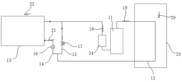
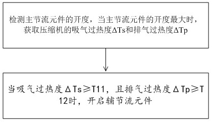
[0059] This embodiment proposes a control method for a space energy heat pump water heater. The space energy heat pump water heater can use solar energy and air energy to heat water, such as figure 1 As shown, it includes a compressor 11, a condenser 12 and an evaporator 13. A main pipeline 14 is connected between the outlet of the condenser 11 and the inlet of the evaporator 13, and is connected between the outlet of the condenser 11 and the outlet of the evaporator 13. The auxiliary pipeline 15, the main pipeline 14 is provided with a main throttling element 16, and the auxiliary pipeline 15 is provided with an auxiliary throttle element 17, such as figure 2 As shown, the control method of the space energy heat pump water heater in this embodiment includes the following steps:

[0060] Detect the opening of the main throttling element 16, and when the opening of the main throttling element 16 is the largest, obtain the suction superheat ΔTs and exhaust superheat ΔTp of the ...

Embodiment 2

[0108] This embodiment proposes a space energy heat pump water heater control system, such as figure 1 As shown, it includes a compressor 11, a condenser 12 and an evaporator 13. A main pipeline 14 is connected between the outlet of the condenser 11 and the inlet of the evaporator 13, and is connected between the outlet of the condenser 11 and the outlet of the evaporator 13. The auxiliary pipeline 15, the main pipeline 14 is provided with a main throttling element 16, and the auxiliary pipeline 15 is provided with an auxiliary throttle element 17. The control method of the space energy heat pump water heater control system in this embodiment can be referred to in the first embodiment records, and will not be repeated here.


PUM


Abstract

The invention discloses a solar and air energy heat pump water heater control method and a system. The solar and air energy heat pump water heater comprises a main pipeline which is connected to a position between an outlet of a condenser and an inlet of an evaporator and an auxiliary pipeline which is connected to a position between an outlet of the condenser and an outlet of the evaporator, a main throttling element is arranged in the main pipeline, and an auxiliary throttling element is arranged in the auxiliary pipeline. The control method comprises the following steps that the opening degree of the main throttling element is detected, and when the opening degree of the main throttling element is maximum, the air suction superheat degree delta Ts and the air exhaust superheat degree delta Tp of a compressor are obtained, and when the air suction superheat degree delta Ts is larger than or equal to T11 and the air exhaust superheat degree delta Tp is larger than or equal to T12, the auxiliary throttling element is started. According to the method, through control, when evaporation overheating occurs, the auxiliary pipeline is opened, one path of refrigerant is throttled and cooled through the auxiliary pipeline, the other path is evaporated through an evaporator, and the evaporated overheating refrigerant and the low-temperature refrigerant throttled through the auxiliary pipeline are mixed and gathered to be sucked into the compressor, so that the air suction temperature is reduced, the air exhaust of the compressor is reduced, and a unit runs more reliably.

Description

technical field [0001] The invention belongs to the technical field of heat pumps, and in particular relates to a control method and system for a space energy heat pump water heater. Background technique [0002] The heat pump water heater or air conditioning system has a fan device, and the evaporation effect of the evaporator is controlled by downshifting or reducing the speed of the fan, or even controlling the start and stop of the fan, so that the evaporation superheat is controlled within a reasonable range and the exhaust gas is prevented from being too high. [0003] At present, some space energy (solar and air energy) heat pump water heaters cancel the fan, which can save costs, mainly through the coating of fins to absorb sunlight and heat exchange through finned tubes and natural convection of air. [0004] Under the conditions of strong sunlight or high ambient temperature with high outdoor wind speed, the heat exchange of the evaporator is too sufficient, and ev...

Claims


Application Information

Patent Timeline
Patent Type & Authority Applications(China)
IPC IPC(8): F24H4/02F24H9/18F24H9/20F25B30/02F25B43/00
CPCF24H4/02F24H9/1809F24H9/2007F25B30/02F25B43/00
Inventor 黄娟李博赵润鹏康乐管祥华余锦剑李羲龙
Owner QINGDAO HAIER NEW ENERGY ELECTRIC APPLIANCE
Why Eureka
Try Eureka