
Standing wave radar state detection device

A state detection device and standing wave technology, applied in radio wave measurement systems, instruments, etc., can solve problems such as inability to accurately detect and receive reflected waves

Pending Publication Date: 2021-05-11
深圳市奔象科技有限公司 +1
View PDF2 Cites 0 Cited by
  • Summary
  • Abstract
  • Description
  • Claims
  • Application Information

AI Technical Summary

Problems solved by technology

[0005] However, the technique of this patent document 1 uses microwave pulse signals, and the time from transmitting radio waves to receiving radio waves is used as the basis to obtain the distance to the reflecting surface.
As mentioned above, considering the speed of the microwave, if the radio wave sensor is not installed at a higher position (such as 10 meters) above the road, it will not be able to receive the reflected wave. In short, there are some problems: such as outdoors When the radio wave sensor is installed in a place where it is necessary to have a rich space at a higher position
However, due to the delay in the radio wave front, it cannot be accurately detected

Method used


Image

  • Standing wave radar state detection device
  • Standing wave radar state detection device
  • Standing wave radar state detection device

Examples


Embodiment Construction

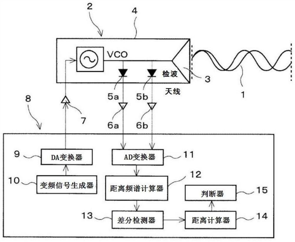
[0090]Hereinafter, embodiments of the present invention will be specifically described with reference to the accompanying drawings.figure 1 It is a histogram of the stational wavelength detection device. The standing wave detector 2 is a constitution of the standing wave radar module, setting 24 GHz high frequency transceiver 4.24GHz high frequency transceiver 4 is 24GHz with VCO (voltage controlled oscillator), with a planned antenna 3 Integrated module. Then, the transceiver 4 is transmitted from the planar antenna 3 from the planar antenna 3 by VCO, and the antenna 3 detects the reflected wave from the detection object being reflected. The two detectors 5a, 5b are hidden in the transceiver 4, detectors 5a, 5b detect transmission waves and reception waves.

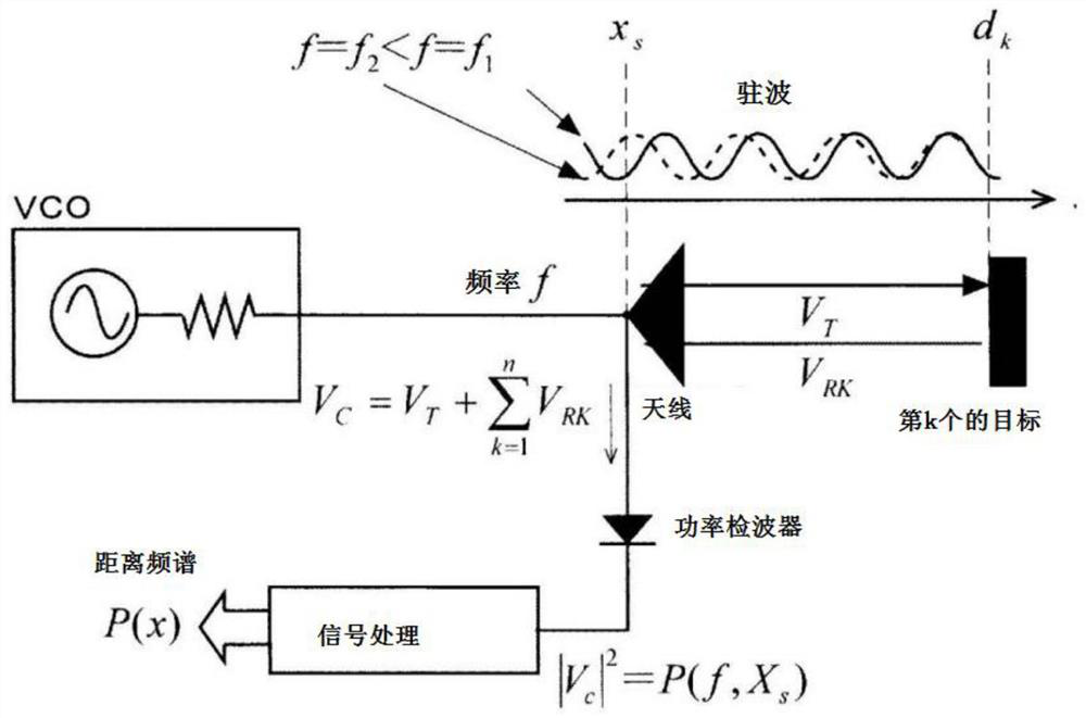
[0091]From the antenna 3 signaling wave 1, when there is a reflective object, the reflected wave returns to the antenna 3, and the same frequency is different from the direction of travel, and the resident wave of the synthesis w...


PUM


Abstract

The invention provides a standing wave radar state detection device. A DC component is removed from the intensity distribution of the number of cycles of a composite wave detected by a standing wave in a distance spectrum arithmetic unit, and conversion is performed to obtain a distance spectrum. In a difference detector, a distance spectrum difference is calculated by subtracting a reference time distance spectrum from the distance spectrum, and a difference distance spectrum over time is calculated. The tip intensity of the differential distance spectrum of the detector changes according to the change of the dielectric constant of the measurement object. Therefore, the state before freezing is detected by reducing the moisture occupancy of the food material to be measured. The controller controls the food material so as to be in a non-frozen state on the basis of the pre-freezing state detected by the detector. Therefore, it is possible to detect changes over time in the moisture or the like of a measurement object, to maintain freshness of food, to find abnormal parts of a human body, to detect the activity of plants, to detect the amount of sweat of a person, and the like.

Description

Technical field[0001]The present invention is a state detecting device using a stand-in-wave radar at the same time to detect the distance between the measurement object.Background technique[0002]Before this, because of the care providers, the caregiver was not allowed to monitor the illness in diaper in the bed. Therefore, the caregiver in order to eliminate the feeling of being uncomfortable to keep cleaning, it can only regularly check the diaper that is seen in the case of the nurse. Moreover, in order to check the degree of drying of the laundry after the cleaning, it can only be checked during the drying of the laundry cleaning. Therefore, the moisture change of the coating continuity cannot be detected, more unable to remotely and over time, the state of the moisture content in the target is detected.[0003]In Patent Document 1, the radio wave sensor transmits an electric wave to the road surface, and the reflective wave of the reflecting surface is received by the above-descr...

Claims


Application Information

Patent Timeline
IPC IPC(8): G01S7/40
CPCG01S7/40
Inventor 斋藤光正斋藤纯辉斋藤真辉雨田基宏青木久佳
Owner 深圳市奔象科技有限公司
Learn More