Vacuum partition flat plate type continuous defoaming machine
A technology of defoaming machine and flat plate, which is applied in the direction of foam dispersion/prevention, etc. It can solve the problems of lack of raw material temperature control, waste of raw materials, secondary pollution of raw materials, etc., and achieve high defoaming treatment efficiency, good defoaming effect, and reduced The effect of cost
- Summary
- Abstract
- Description
- Claims
- Application Information
AI Technical Summary
Problems solved by technology
Method used
Image
Examples
Embodiment 1
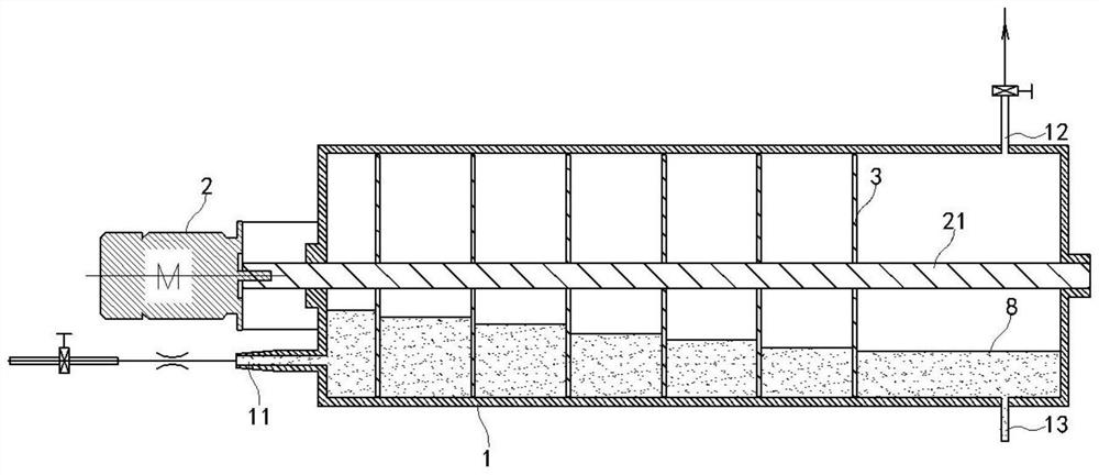
[0046] like figure 1 As shown, a vacuum partition flat plate continuous degassing machine of the present embodiment comprises a horizontally arranged cylindrical separation tank 1, and the separation tank 1 is provided with a feed pipe 11, a vacuum pipe 12 and a discharge port 13; Set the main shaft 21 coaxial with the separation tank 1, the main shaft 21 and the two ends of the separation tank 1 are connected by bearings, the end of the separation tank 1 is provided with a motor 2 to drive the main shaft 21 to rotate; the main shaft 21 is provided with six equally spaced belt discs 3. The disc 3 with material is rotated and sealed with the inner wall of the separation tank 1 to divide the interior of the separation tank 1 into seven chambers, and the disc 3 with material is provided with a discharge hole 31 to communicate with two adjacent chambers.
[0047] In this embodiment, the separation tank 1 is first evacuated through the vacuum tube 12, the slurry 8 enters the separ...
Embodiment 2
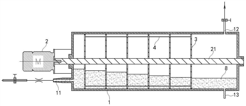
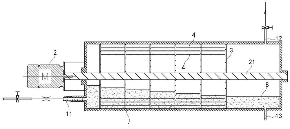
[0050] like figure 2As shown, in this embodiment, as a further optimization of Embodiment 1, a hollow defoaming column 4 with a mesh 41 is arranged between two adjacent discs 3 with material, the defoaming column 4 is coaxial with the main shaft 21, and the defoaming column 4 With the rotation of the disc 3 with the material, the defoaming column 4 can simultaneously perform thin film defoaming on the slurry 8 in the chamber, thereby increasing the thin film area, increasing the defoaming efficiency and defoaming effect.
Embodiment 3
[0052] like Figure 4 As shown, this embodiment is further optimized as Embodiment 1. The outer surface of the separation tank 1 is provided with a cooling and heating medium circulation chamber 5, and the cooling and heating medium circulation chamber 5 is provided with a cooling and heating medium inlet 52 or a cooling and heating medium outlet 51. A cold and hot medium outlet 51 or a cold and hot medium inlet 52 is arranged below the medium circulation chamber 5, and the temperature in the separation tank 1 can be adjusted by passing in a refrigerant or a heat medium, so that the separation tank 1 is always in the process temperature range for the degassing of the slurry 8, and more It is beneficial to the defoaming of the slurry 8.
PUM
 Abstract
Description
Claims
Application Information
 - R&D
- Intellectual Property
- Life Sciences
- Materials
- Tech Scout
- Unparalleled Data Quality
- Higher Quality Content
- 60% Fewer Hallucinations
Browse by: Latest US Patents, China's latest patents, Technical Efficacy Thesaurus, Application Domain, Technology Topic, Popular Technical Reports.
© 2025 PatSnap. All rights reserved.Legal|Privacy policy|Modern Slavery Act Transparency Statement|Sitemap|About US| Contact US: help@patsnap.com


