
Ultrafiltration membrane filter element with pre-membrane gas exhaust device

A technology of exhaust device and ultrafiltration membrane, applied in ultrafiltration, membrane technology, semi-permeable membrane separation, etc. Utilization and other issues, to achieve the effect of easy disassembly and replacement, easy disassembly and installation, and easy removal

Inactive Publication Date: 2021-05-14
黄佳翔
View PDF0 Cites 0 Cited by
  • Summary
  • Abstract
  • Description
  • Claims
  • Application Information

AI Technical Summary

Problems solved by technology

[0003] However, in the process of ultrafiltration membrane filter element filtration, often due to the morphology and structure of the ultrafiltration membrane, it is difficult to remove the gas in front of the ultrafiltration membrane, especially after the ultrafiltration membrane is soaked in water, the gas in front of the membrane is completely blocked. The gas in front of the ultrafiltration membrane forms air resistance in the ultrafiltration membrane element, making it difficult for the interior of the ultrafiltration membrane to be completely submerged in water, which affects the utilization rate of the ultrafiltration membrane. Cleaning the ultrafiltration membrane element will affect the performance and life of the ultrafiltration membrane, and the common cleaning method is often to rinse with water, but the nature of the liquid treated by the ultrafiltration membrane element is different, resulting in insufficient cleaning , thereby affecting the filtering effect of re-use

Method used


Image

  • Ultrafiltration membrane filter element with pre-membrane gas exhaust device
  • Ultrafiltration membrane filter element with pre-membrane gas exhaust device
  • Ultrafiltration membrane filter element with pre-membrane gas exhaust device

Examples


Embodiment Construction

[0026] The following will clearly and completely describe the technical solutions in the embodiments of the present invention with reference to the accompanying drawings in the embodiments of the present invention. Obviously, the described embodiments are only some, not all, embodiments of the present invention. The specific embodiments described here are only used to explain the present invention, and are not intended to

[0027] to limit the present invention. Based on the embodiments of the present invention, all other embodiments obtained by persons of ordinary skill in the art without making creative efforts belong to the protection scope of the present invention.

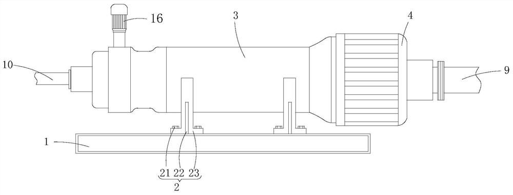
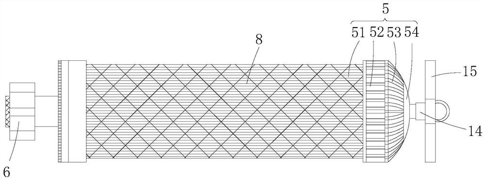
[0028] The present invention provides such Figure 1-5 The shown ultrafiltration membrane filter element with a pre-membrane gas exhaust device includes a mounting plate 1, and the top surface of the mounting plate 1 is equipped with a mounting cylinder 3 through a mounting mechanism 2. The mounting mechanism...


PUM


Abstract

The invention discloses an ultrafiltration membrane filter element with a before-membrane gas exhaust device, and belongs to the field of ultrafiltration membrane filter elements, the ultrafiltration membrane filter element comprises a mounting plate, a mounting cylinder is mounted on the top surface of the mounting plate through a mounting mechanism, one end mounted in the mounting cylinder is in threaded connection with the inner side wall of a cylinder cover, a water inlet pipe is arranged at one end of the cylinder cover, and a water outlet pipe is arranged at the other end of the cylinder cover. A second water outlet pipe is arranged at the other end of the mounting cylinder, a filter element is mounted in the mounting cylinder, and an exhaust mechanism is fixedly connected to one end of the filter element; and the other end of the filter element is rotationally connected with a limiting mechanism. According to the ultrafiltration membrane filter element with the pre-membrane gas exhaust device, the exhaust cover is fixedly connected to one end of the filter element, and the first water tank is formed in the side wall of the filter element, so that gas resistance on the side wall of an ultrafiltration membrane is reduced; and the filter element is driven by the motor to rotate in the mounting cylinder, so that the filter element is conveniently cleaned.

Description

technical field [0001] The invention belongs to the technical field of ultrafiltration membrane filter elements, in particular to an ultrafiltration membrane filter element with a pre-membrane gas exhaust device. Background technique [0002] The ultrafiltration membrane is a polymer semipermeable membrane used in the ultrafiltration process to separate polymer colloids or suspended particles of a certain size from the solution. The ultrafiltration membrane screening process is driven by pressure difference. The high-precision cut-off performance of the filter membrane is a membrane separation technology for solid-liquid separation or fractionation of substances with different relative molecular masses. Under a certain pressure, when the mixed solution containing high-molecular solute and low-molecular solute flows through the surface of the membrane, the solvent and low-molecular solute (such as inorganic salt) that are smaller than the membrane pores pass through the membr...

Claims


Application Information

Patent Timeline
Patent Type & Authority Applications(China)
IPC IPC(8): B01D61/14B01D61/16B01D61/18B01D61/20B01D63/06B01D65/02C02F1/20C02F1/44
CPCB01D61/145B01D61/16B01D61/18B01D61/20B01D63/06B01D65/02C02F1/20C02F1/444C02F2303/14
Inventor 黄佳翔
Owner 黄佳翔
Learn More