Energy-saving and environment-friendly animal waste recycling, drying and combustion treatment equipment

A technology for animal excrement and treatment equipment, which is used in dewatering/drying/concentrating sludge treatment, pyrolysis treatment sludge, animal husbandry wastewater treatment, etc. Effect

Inactive Publication Date: 2021-05-14
深圳市中禾商务顾问有限公司
View PDF7 Cites 4 Cited by
  • Summary
  • Abstract
  • Description
  • Claims
  • Application Information

AI Technical Summary

Problems solved by technology

[0004] In order to overcome the shortcomings that the burner in the closed state cannot observe the combustion situation, it takes a long time to burn a large amount of excrement at one time, and the burner needs to be opened to collect dust later, the purpose of the present invention is to provide an open combustion Environment, intermittent feeding of feces, continuous combustion, real-time push out of dust, easy to collect energy-saving and environmentally friendly animal feces recovery drying combustion treatment equipment

Method used


Image

  • Energy-saving and environment-friendly animal waste recycling, drying and combustion treatment equipment
  • Energy-saving and environment-friendly animal waste recycling, drying and combustion treatment equipment
  • Energy-saving and environment-friendly animal waste recycling, drying and combustion treatment equipment

Examples


Embodiment 1

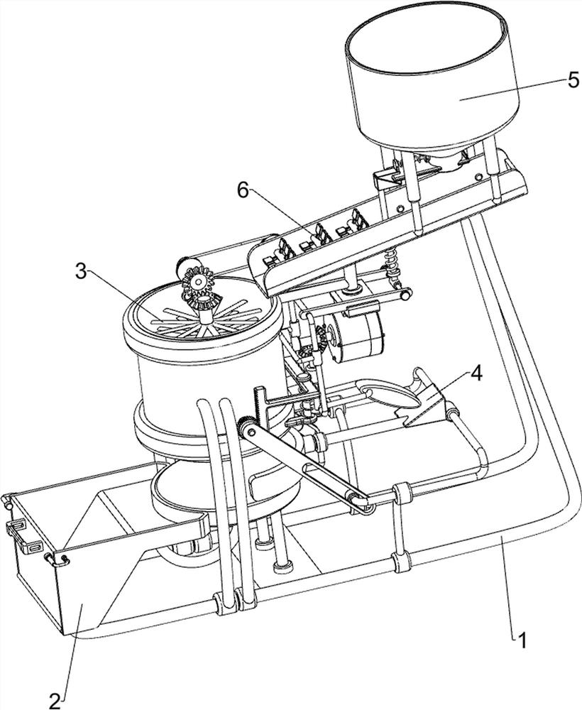
[0047] A kind of energy-saving and environment-friendly animal manure recovery dry burning treatment equipment, such as Figure 1 to Figure 3 As shown, a combustion mechanism 1 and a collection mechanism 2 are included, and the combustion mechanism 1 is connected with the collection mechanism 2 .

[0048] The combustion mechanism 1 includes a first fixed frame 11, a first support rod 12, a combustion barrel 13, a second support rod 14 and a placement plate 15, and the left part of the first fixed frame 11 is symmetrically provided with a first support rod 12. A combustion barrel 13 is connected between the tops of the rods 12, and there are 2 discharge holes on the left side of the bottom of the combustion barrel 13. The top of the first fixed frame 11 is symmetrically provided with a second support rod 14, and the top of the second support rod 14 is connected with a Place plate 15, and place plate 15 is positioned at combustion bucket 13 below.

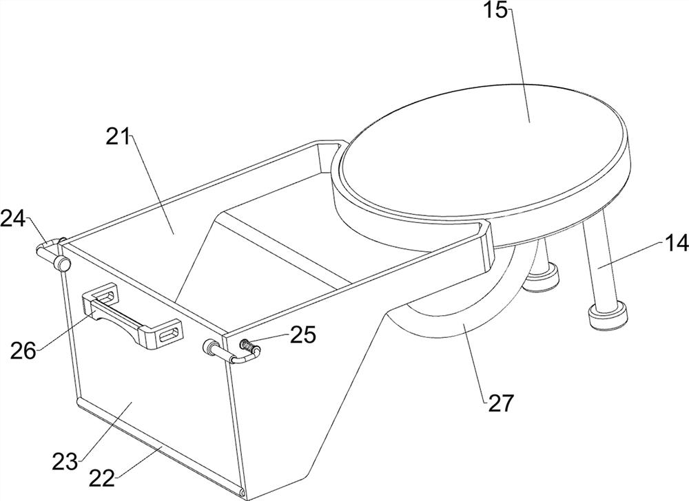
[0049] The collection mechan...

Embodiment 2

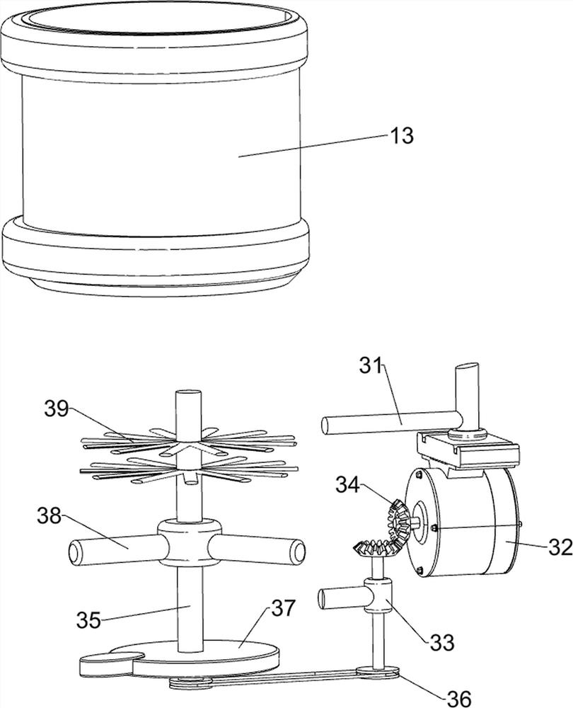
[0052] On the basis of Example 1, such as Figure 4 and Figure 5As shown, a rotating mechanism 3 is also included, and the rotating mechanism 3 includes a second fixed rod 31, a motor 32, a third fixed rod 33, a first bevel gear set 34, a second rotating shaft 35, a first transmission assembly 36, a first Cam 37, the second fixed frame 38 and rotating piece 39, the right side of the upper part of the combustion barrel 13 is connected with the second fixed rod 31, the second fixed rod 31 is provided with a motor 32, and the right side of the lower part of the combustion barrel 13 is connected with the third fixed rod 33, the right part of the third fixed rod 33 is connected with the first bevel tooth group 34 between the short rod and the output shaft of the motor 32, the inner wall of the combustion barrel 13 is connected with the second fixed frame 38, and the second fixed frame 38 is connected in a rotating manner There is a second rotating shaft 35, a first transmission a...

Embodiment 3

[0056] On the basis of Example 2, such as Figure 6 and Figure 7 Shown, also include unloading mechanism 5, unloading mechanism 5 includes the seventh fixed rod 51, push frame 52, the 3rd spring 53, slide plate 54, unloading barrel 55, baffle plate 56 and the 4th spring 57, combustion The seventh fixed rod 51 is symmetrically arranged on the right side of the upper part of the bucket 13, and a push frame 52 is slidably connected between the seventh fixed rods 51. The push frame 52 cooperates with the push rod 49, and a slide plate 54 is connected to the right side of the top of the first fixed frame 11. , the right part of the slide plate 54 is connected with the lower material barrel 55, the lower part of the lower material barrel 55 is slidingly connected with the baffle plate 56, the fourth spring 57 is connected between the top of the baffle plate 56 and the lower material barrel 55, and the middle part of the baffle plate 56 is slidingly connected. There is a wedge, the...


PUM


Abstract

The invention relates to combustion treatment equipment, in particular to energy-saving and environment-friendly animal waste recycling, drying and combustion treatment equipment. The invention mainly provides energy-saving and environment-friendly animal waste recycling, drying and burning treatment equipment which provides an open burning environment, intermittently discharges and continuously burns waste, pushes out dust in real time and is convenient to collect. The energy-saving and environment-friendly animal waste recycling, drying and burning treatment equipment comprises a collecting mechanism, wherein a burning mechanism is connected with the collecting mechanism. Through the arrangement of the combustion mechanism and the rotating mechanism, the excrement is combusted after being minced, and the basic functions of the equipment are achieved; by arranging the collecting mechanism and the pushing mechanism, the combusted excrement is pushed and collected; by arranging the discharging mechanism and the conveying mechanism, intermittent discharging is conducted on excrement, manual pushing is not needed, and safety is guaranteed.

Description

technical field [0001] The invention relates to a combustion treatment device, in particular to an energy-saving and environment-friendly recycling and drying combustion treatment device for animal manure. Background technique [0002] With the increase in the number of breeding industries, a large amount of animal manure has become a major source of pollution affecting the local environment. At present, manure is mainly used to produce organic fertilizers and directly as fuel, but the efficiency is not high. Manure is compressed into various The shape of the fuel reduces the humidity of the feces and is conducive to the full combustion of the feces. [0003] In order to ensure the quality of combustion, the traditional burner is in a closed state during combustion, and the combustion situation cannot be observed. It takes a long time to burn a large amount of feces at one time. Contents of the invention [0004] In order to overcome the shortcomings that the burner in th...

Claims


Application Information

Patent Timeline
Patent Type & Authority Applications(China)
IPC IPC(8): C02F11/12C02F11/10C02F11/18C02F103/20
CPCC02F11/13C02F11/10C02F11/18C02F2103/20
Inventor 丁秀亭
Owner 深圳市中禾商务顾问有限公司
Why Eureka
Try Eureka