Cracking gas separation system and method adopting absorption-desorption

A separation method and separation system technology, applied in the field of cracking gas separation, can solve the problems of high energy consumption and large process investment, and achieve the effects of low energy consumption, lower investment and lower energy consumption

Pending Publication Date: 2021-05-14
CHINA PETROLEUM & CHEM CORP +1
View PDF4 Cites 0 Cited by
  • Summary
  • Abstract
  • Description
  • Claims
  • Application Information

AI Technical Summary

Problems solved by technology

[0006] In order to solve the problems of large process investment and high energy consumption in the prior art, the present invention provides a cracking gas separation system and method using absorption-desorption

Method used


Image

  • Cracking gas separation system and method adopting absorption-desorption
  • Cracking gas separation system and method adopting absorption-desorption

Examples


Embodiment 1

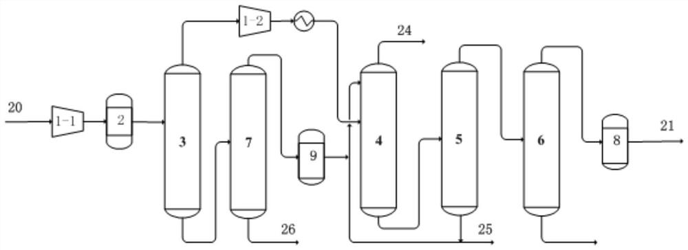
[0081]Usefigure 1 A cleavage gas separation system, including: compressor (compressor front section 1-1, compressor post section 1-2); purifying system 2; Decarburized four tower 3; absorption tower 4; desorption tower 5; Propylene column 6; rehabilitating tower 7; carbon dihydrogenation reactor 8; carbon four hydrogenation reactor 9.

[0082]Compressor segment is sequentially connected to the purification system 2 and the decarbonate four-7 tower 3, the decarbonate four-tower 3-top connection compressor post-concatenator 1-2 connection absorption tower 4, decarbonate four tower 3 kettle connection to the heavy tower; Tower 7 column top ligation carbon tetrahydrogenated reactor 9, carbon four hydrogenation reactor 9 outlet line and the desorbing tower 5 column outlet line After combining the absorption tower 4 upper;

[0083]Absorption Tower 4 Tower Connection Tower 5; Decoction Tower 5 Tower Top Connectation Depropino Tower 6, Decoction Total 5 Tower and Carbon Fetal Hydrogen Reactor 9 O...

Embodiment 2

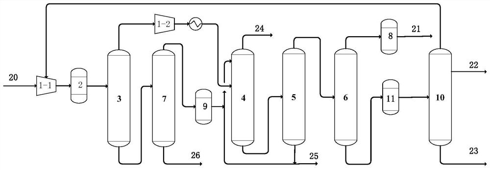
[0104]Usefigure 2 A cleavage gas separation system, including: compressor (compressor front section 1-1, compressor post section 1-2); purifying system 2; Decarburized four tower 3; absorption tower 4; desorption tower 5; Propylene tower 6; rehabilitating tower 7; carbon dihydrogenation reactor 8; carbon four hydrogenation reactor 9; propylene rectification column 10; carbon trihydrofluorice 11.

[0105]Compressor segment is sequentially connected to the purification system 2 and the decarbonate four-7 tower 3, the decarbonate four-tower 3-top connection compressor post-concatenator 1-2 connection absorption tower 4, decarbonate four tower 3 kettle connection to the heavy tower; Tower 7 column top ligation carbon tetrahydrogenated reactor 9, carbon four hydrogenation reactor 9 outlet line and the desorbing tower 5 column outlet line After combining the absorption tower 4 upper;

[0106]Absorption Tower 4 Tower Connection Tower 5; Decoction Tower 5 Tower Top Connectation Depropino Tower 6,...


PUM


Abstract

The invention discloses a cracking gas separation system and method adopting absorption-desorption. The system comprises a compressor, a purification system, a C4 removal tower, an absorption tower, a desorption tower, a depropanization tower, a heavy component removal tower, a C2 hydrogenation reactor and a C4 hydrogenation reactor, wherein the purification system and the C4 removal tower are sequentially connected between the compressor sections, the C4 removal tower top is connected with the rear section of the compressor and then connected with the absorption tower, and the C4 removal tower kettle is connected with the heavy component removal tower; the tower top of the heavy component removal tower is connected with the C4 hydrogenation reactor; an outlet pipeline of the C4 hydrogenation reactor and a tower kettle outlet pipeline of the desorption tower are combined and then connected with the upper part of the absorption tower; the absorption tower kettle is connected with a desorption tower; the top of thedesorption tower is connected with thedepropanization tower, a tower kettle of the desorption tower is combined with an outlet pipeline of the C4 hydrogenation reactor and then is connected with the upper part of the absorption tower; and the top of the depropanization tower is connected with a C2 hydrogenation reactor. The system has the characteristics of low investment, low energy consumption and remarkable benefit.

Description

Technical field[0001]The present invention relates to the field of cleavage gas separation technology, and further, it is to relate to a cleavage gas separation system and method using absorption-desorption.Background technique[0002]A large amount of exhaust gas is generated during refining and chemical production, there are some exhaust gas, such as catalytic cracking, thermal cracking, latency coking, hydrocracking, etc., contains many carbon two, carbon three components, especially some exhaust gas. The ethane / propane content is relatively high. At present, the carbon diopoly-three refiner is currently recovered from the refinery exhaust gas, mainly to the different sections of the vinyl plant, used to increase the vinyl propylene, however, for the refinery without an ethylene production device, it is concentrated Going is a major problem, causing the carbon di-carbon three resources in dry gas to be fully utilized, resulting in greater waste.[0003]The most important way to uti...

Claims


Application Information

Patent Timeline
IPC IPC(8): C07C7/00C07C7/04C07C7/163C07C7/167C07C7/11C07C11/04C07C11/06C07C5/03C10G5/04
CPCC07C7/005C07C7/04C07C7/163C07C7/167C07C7/11C07C5/03C10G5/04C07C11/04C07C11/06C07C9/08Y02P30/40
Inventor 田峻李春芳罗淑娟张敬升常大山王宇飞
Owner CHINA PETROLEUM & CHEM CORP
Why Eureka
Try Eureka