
Dual-injection turbulent jet ignition pre-chamber device for spark ignition engine

A technology of turbulent jet flow and pre-combustion chamber, which is applied to fuel injection devices, combustion engines, internal combustion piston engines, etc., and can solve problems such as the inability to stably form jet flames, misfires, and deterioration of emissions

Pending Publication Date: 2021-05-14
TIANJIN UNIV
View PDF8 Cites 5 Cited by
  • Summary
  • Abstract
  • Description
  • Claims
  • Application Information

AI Technical Summary

Problems solved by technology

For the working condition of high EGR rate, the proportion of exhaust gas in the pre-combustion chamber is relatively high, and the oxygen concentration is low, which makes it difficult to ignite in the pre-combustion chamber and cannot stably form a jet flame, which may easily cause misfire, affect the thermal efficiency of the engine, and worsen emissions; low EGR Under high-speed working conditions, after ignition, the flame development speed in the pre-combustion chamber slows down, delaying the combustion process, resulting in a decrease in the intensity and speed of the jet flame, and a worsening of the ignition effect, which weakens the improvement and promotion of the jet flame on the combustion process of the mixture in the main combustion chamber

Method used


Image

  • Dual-injection turbulent jet ignition pre-chamber device for spark ignition engine
  • Dual-injection turbulent jet ignition pre-chamber device for spark ignition engine
  • Dual-injection turbulent jet ignition pre-chamber device for spark ignition engine

Examples


Embodiment Construction

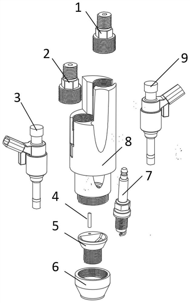
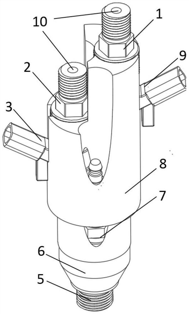
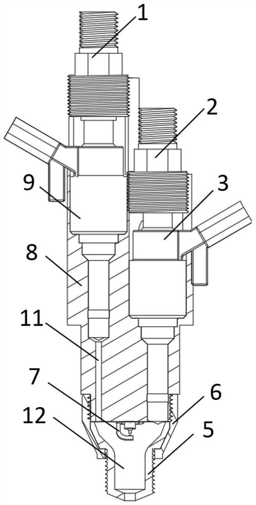
[0022] The present invention proposes a multi-mode turbulent jet ignition pre-combustion chamber device for an ignition type engine, which mainly consists of compression bolts 1, 2, fuel injector 3, gas injector 9, compression bolt through hole 10, air channel 11. The pre-chamber upper cavity 8, the pre-chamber inner cavity 12, the pre-chamber nozzle 5, the pre-chamber nozzle pressing part 6, the spark plug 7, the positioning pin 4 and other parts. All structures and working principles of the pre-chamber device will be described in detail below with reference to the accompanying drawings.

[0023] attached figure 1 Exploded view of the parts of the multi-mode turbulent jet ignition pre-chamber device proposed by the present invention. Both ends of the compression bolt are threaded and have a through hole, and the thread at one end is connected to the upper chamber 8 of the pre-chamber, and is used to fix and seal the fuel injector 3 and the gas injector 9 on the upper chamber...


PUM


Abstract

The invention provides a dual-injection type turbulent jet ignition pre-combustion chamber device for a spark ignition engine. The dual-injection type turbulent jet ignition pre-combustion chamber device comprises two compression bolts, a fuel injector (3), a gas injector (9), a pre-combustion chamber upper cavity (8), a pre-combustion chamber nozzle (5), a pre-combustion chamber nozzle compression piece (6) and a spark plug (7). The spark plug (7), the fuel injector (3) and the gas injector (9) are fixed in the pre-combustion chamber upper cavity (8), and each of the fuel injector (3) and the gas injector (9) is fixed in the pre-combustion chamber upper cavity (8) through a compression bolt; each compression bolt is provided with a through hole (10), two ends of each compression bolt are provided with threads, one end of each compression bolt is connected with the pre-combustion chamber upper cavity (8) through the threads and used for fixing the gas injector (9) or the fuel injector (3), and the other end of each compression bolt is connected with a gas path or a fuel path; and the pre-combustion chamber nozzle (5) is pressed by the pre-combustion chamber nozzle compression piece (6) and is fixed to the lower end of the pre-combustion chamber upper cavity (8) to form a pre-combustion chamber inner cavity (12).

Description

technical field [0001] The invention relates to the technical field of internal combustion engine combustion, and relates to a multi-mode turbulent jet ignition pre-combustion chamber device for ignition engines. Background technique [0002] The intensification of environmental pollution has made the emission problems faced by internal combustion engines more severe! In order to limit the emissions of internal combustion engines, governments and international organizations have enacted more stringent emission regulations. How to improve the thermal efficiency of internal combustion engines while reducing emissions has become a hot topic worldwide. Exhaust gas recirculation (EGR) technology is a technology that separates part of the exhaust gas discharged after in-cylinder combustion and introduces it into the intake side, so that it can participate in in-cylinder combustion again. The main purpose is to improve the fuel economy of the engine under partial load performance...

Claims


Application Information

Patent Timeline
IPC IPC(8): F02B19/10F02B19/12F02M21/02F02M61/14F02D41/30F02B25/00
CPCF02B19/1066F02B19/1071F02B19/108F02B19/12F02M21/0281F02M61/14F02D41/3094F02D41/0025F02B25/00Y02T10/12Y02T10/30
Inventor 周磊刘宗宽高强华剑雄卫海桥
Owner TIANJIN UNIV
Learn More