Accumulative temperature difference controlled loop heat pipe solar system
A loop heat pipe and liquid level difference technology, applied in the field of solar energy, can solve the problem of too long hysteresis period, and achieve the effects of improving heat release capacity, improving heat exchange efficiency, and increasing vibration range
- Summary
- Abstract
- Description
- Claims
- Application Information
AI Technical Summary
Problems solved by technology
Method used
Image

Examples
Embodiment Construction
[0042] The specific embodiments of the present invention will be described in detail below in conjunction with the accompanying drawings.
[0043] In this article, if there is no special explanation, when it comes to formulas, " / " means division, and "×" and "*" mean multiplication.
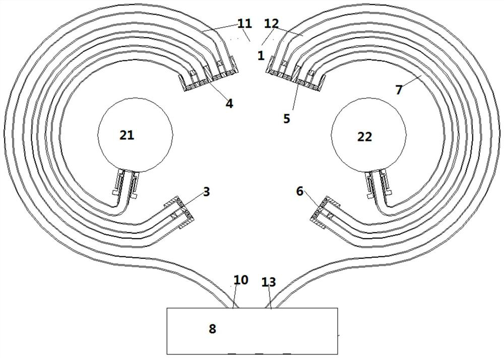
[0044] Such as figure 1As shown, a kind of heat collecting device comprises heat collecting tube box 8, left upper tube 21, right upper tube 22 and heat radiation tube group 1, and described heat radiation tube group 1 comprises left heat radiation tube group 11 and right heat radiation tube group 12, left heat radiation tube Group 11 communicates with the left upper tube 21 and the heat collecting tube box 8, and the right heat releasing tube group 12 communicates with the right upper tube 22 and the heat collecting tube box 8, so that the heat collecting tube box 8, the left upper tube 21, the right upper tube 22 and the heat releasing tube group 1 A closed loop of heating fluid is formed, and...
PUM
 Abstract
Description
Claims
Application Information
 - Generate Ideas
- Intellectual Property
- Life Sciences
- Materials
- Tech Scout
- Unparalleled Data Quality
- Higher Quality Content
- 60% Fewer Hallucinations
Browse by: Latest US Patents, China's latest patents, Technical Efficacy Thesaurus, Application Domain, Technology Topic, Popular Technical Reports.
© 2025 PatSnap. All rights reserved.Legal|Privacy policy|Modern Slavery Act Transparency Statement|Sitemap|About US| Contact US: help@patsnap.com