Method for intelligently detecting defective glass image, electronic equipment and storage medium

An intelligent detection and image technology, applied in image enhancement, image analysis, image data processing, etc., can solve problems such as unfavorable data backtracking, inconvenient defect data storage, cutting linear fluctuations, etc., to reduce the risk of entering the market and improve products Detection efficiency, the effect of improving work efficiency

Active Publication Date: 2021-05-14
高视科技(苏州)股份有限公司
View PDF9 Cites 3 Cited by
  • Summary
  • Abstract
  • Description
  • Claims
  • Application Information

AI Technical Summary

Problems solved by technology

[0003] In the Thin film transistor liquid crystal display (TFT-LCD) industry, because the production of large-size glass substrates can effectively improve the yield and output rate of large-screen LCD panels, while reducing production costs, so in In the production process, the glass substrate is always enlarged, and then cut according to the actual production needs. The four sides of the cut glass are required to be straight lines, which is an important control parameter in the glass production process; Fine cutting knife wheel and movement, the straightness of edge cutting will fluctuate, and there will be local protrusions or depressions on the edge, resulting in fragments, under-grinding, burning edges, cracks, etc., which seriously affect product quality
[0004] At present, the measurement method of defective glass is often measured by personnel operating a vernier caliper or a two-dimensional image measuring instrument, and adjusted according to the four-sided linearity measurement data. The application of these two methods makes the entire adjustment process more cumbersome, longer detection time, and poor operability. , the measurement data is inaccurate, and it is inconvenient to save defect data, which is not conducive to data backtracking

Method used


Image

  • Method for intelligently detecting defective glass image, electronic equipment and storage medium
  • Method for intelligently detecting defective glass image, electronic equipment and storage medium
  • Method for intelligently detecting defective glass image, electronic equipment and storage medium

Examples


Embodiment ( Embodiment 1

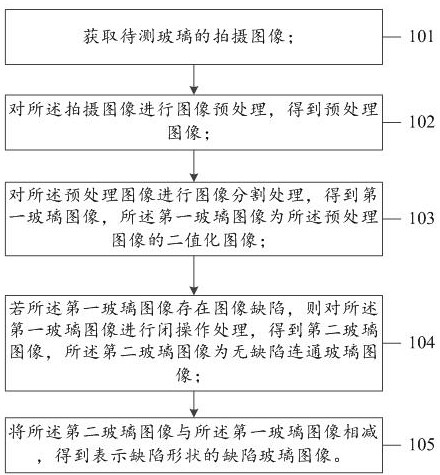
[0056] see figure 1 , an embodiment (Embodiment 1) of the method for intelligently detecting defective glass images in the embodiment of the present application includes:

[0057] 101. Obtain a photographed image of the glass to be tested;

[0058] In this embodiment, in the captured images of the glass to be tested, the glass to be tested is the glass that has been cut and separated, and each glass has a corresponding product serial number; in order to improve the product quality of the glass that leaves the factory, it is necessary Detect the glass on the cut surface, and record the information of the cut surface; for example, identify the product serial number of the glass product through a code reader, and use an image sensor to obtain an edge image of the cut glass (that is, a captured image of the glass to be tested); Wherein, the glass to be tested is a regular rectangular panel with four cutting surfaces, and each cutting surface needs to be detected, and each cutting...

Embodiment ( Embodiment 2

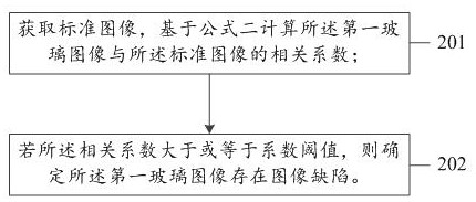
[0084] see figure 2 , the second embodiment (embodiment 2) of the method for intelligently detecting defective glass images in the embodiment of the present application includes:

[0085] 201. Acquire a standard image, and calculate a correlation coefficient between the first glass image and the standard image based on Formula 1;

[0086] In this embodiment, the standard image refers to a non-defective glass image, which is determined according to the customer's quality requirements for the image; defect image, it is necessary to calculate the correlation coefficient between the standard image and the first glass image (that is, the binarized image), and then determine whether it is a defect image according to the size of the correlation coefficient; in practical applications, the correlation coefficient is based on formula 1 Calculation, the following is the expression of Formula 1:

[0087]

[0088] Wherein, NCC represents the correlation coefficient between the standa...

Embodiment ( Embodiment 3

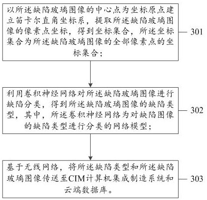
[0093] see image 3 , the third embodiment (Embodiment 3) of the method for intelligently detecting defective glass images in the embodiment of the present application includes:

[0094] 301. Establish a Cartesian coordinate system with the center point of the defective glass image as the coordinate origin, extract the pixel point coordinates of the defective glass image, and obtain a coordinate set, and the coordinate set is all the pixel points of the defective glass image set of coordinates;

[0095] In this embodiment, in order to conveniently determine the defect position of the defect image, it is necessary to locate the defect image, and the defect image positioning is used to quickly find the defect position of the glass product, which is convenient for realizing physical repair and finding and determining the edge of the glass cutting edge. Causes of defects, reduce the product error rate of cut glass; the image acquired by the sensor is a rectangular image, there ar...


PUM


Abstract

The invention relates to a method for intelligently detecting a defective glass image. The method comprises the following steps: acquiring a shot image of to-be-detected glass; performing image preprocessing on the shot image to obtain a preprocessed image; performing image segmentation processing on the preprocessed image to obtain a first glass image; if the first glass image has the image defect, performing closed operation processing on the first glass image to obtain a second glass image; and subtracting the first glass image from the second glass image to obtain a defective glass image representing the shape of the defect. According to the scheme provided by the invention, the cut glass edge image is automatically detected, so that errors caused by manual measurement are avoided, the product detection efficiency of a glass production line can be improved, the risk that defective glass products flow into the market due to uneven cutting is further reduced, and the product quality is improved.

Description

technical field [0001] The present application relates to the technical field of defective glass image detection, and in particular to a method for automatically detecting defective glass images, electronic equipment and storage media. Background technique [0002] Glass has been around for thousands of years and is one of the most versatile man-made materials in high-tech. In the screen display industry, liquid crystal glass is a high-tech optoelectronic glass product formed by encapsulating liquid crystal in glass through high temperature and high pressure. Nowadays, liquid crystal glass is widely used as a dimming device for electronic equipment, and the upper and lower polarizing plates are attached after the color film is formed into a box, and the bottom is added with a backlight to form a liquid crystal display (LCD for short). An important part of the current display device. [0003] In the Thin film transistor liquid crystal display (TFT-LCD) industry, because the...

Claims


Application Information

Patent Timeline
Patent Type & Authority Applications(China)
IPC IPC(8): G06T7/00G06T7/11G06T7/13G06T7/136G06T7/187G06T5/30G06T5/00
CPCG06T5/002G06T5/30G06T7/0004G06T7/11G06T7/13G06T7/136G06T7/187
Inventor 陈奕舜范伟华邹伟金
Owner 高视科技(苏州)股份有限公司
Why Eureka
Try Eureka