Tail gas treatment device for underground engineering construction machinery

A technology for construction machinery and underground engineering, which can be used in exhaust devices, mechanical equipment, mufflers, etc., and can solve problems such as hazards

Pending Publication Date: 2021-05-18
查昀
View PDF4 Cites 0 Cited by
  • Summary
  • Abstract
  • Description
  • Claims
  • Application Information

AI Technical Summary

Problems solved by technology

[0005] The object of the present invention is to provide an exhaust gas treatment device for underground engineering construction machinery that can effe

Method used


Image

  • Tail gas treatment device for underground engineering construction machinery
  • Tail gas treatment device for underground engineering construction machinery

Examples


Embodiment 1

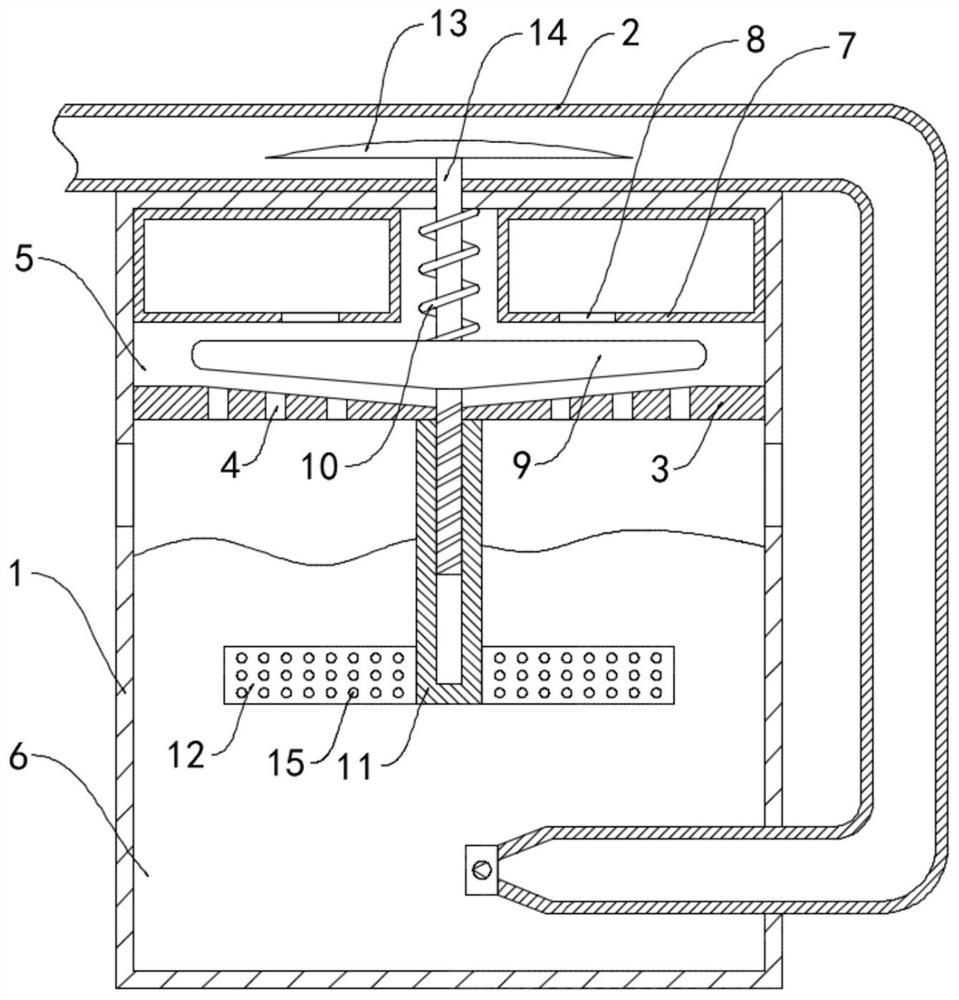
[0024] Such as figure 1 As shown, an exhaust gas treatment device for underground engineering construction machinery includes a housing 1 and an air intake pipe 2 fixedly connected to the housing 1. The air intake pipe 2 communicates with the end of the exhaust gas discharge pipe of the underground engineering construction machinery. A horizontal sieve plate 3 is fixedly connected to the wall, and a plurality of sieve holes 4 are equidistantly arranged in the sieve plate 3 .

[0025] Further, the top surface of the material storage chamber 5 is fixedly connected with an annular material storage box 7, and the annular material storage box 7 is filled with scavenger particles, the scavenger particles are sodium hydroxide solid particles, and the bottom of the annular material storage box 7 is provided with A horizontal grinding plate 9 is provided below the discharge port 8 and the annular material storage box 7 , and the grinding plate 9 is fixedly connected to the top surface ...

Embodiment 2

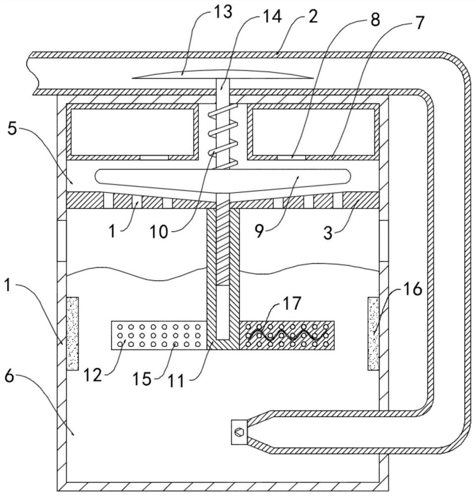
[0033] Such as figure 2 As shown, the difference between this embodiment and Embodiment 1 is that: the inner wall of the clean chamber 6 is fixedly connected with a permanent magnet ring 16, the spoiler 12 is embedded with a helical coil 17, and the two conductive ends of the helical coil 17 They are connected to each other to form a closed loop, and the winding direction of the helical coil 17 is perpendicular to the direction of the magnetic field line of the permanent magnetic ring 16 .

[0034] In this embodiment, when the helical coil 17 rotates synchronously with the spoiler 12, the magnetic induction lines of the permanent magnetic ring 16 are continuously cut to generate an induced current, and the electric energy is converted into heat energy to generate heat, and the alkaline solution is heated to accelerate the process of the alkaline solution. The evaporation rate of the solvent water increases the concentration of the alkaline solution. At the same time, water is...


PUM


Abstract

The invention belongs to the field of underground engineering construction, and particularly relates to a tail gas treatment device for underground engineering construction machinery, which comprises a shell and a gas inlet pipe fixedly communicated with the shell; the gas inlet pipe is communicated with the tail end of a tail gas discharge pipe of the underground engineering construction machinery; a horizontally-arranged sieve plate is fixedly connected to the inner side wall of the shell, a plurality of sieve holes are formed in the sieve plate at equal intervals, the interior of the shell is divided into a material storage cavity and a purification cavity through the sieve plate, an annular material storage box is fixedly connected to the top face of the material storage cavity, and purifying agent particles are contained in the annular material storage box. According to the tail gas purification device, an alkaline solution can absorb acid gas in tail gas to generate an acid-base neutralization reaction, and a good tail gas purification effect is achieved; by arranging the wing plates, a purifying agent can be continuously added into the purification cavity; meanwhile, the alkaline solution is stirred and disturbed, the contact area and probability of harmful tail gas and the alkaline solution are increased, and the purification effect of the tail gas purification device is further improved.

Description

technical field [0001] The invention belongs to the field of underground engineering construction, in particular to a tail gas treatment device for underground engineering construction machinery. Background technique [0002] Underground engineering refers to the underground civil engineering that goes deep below the ground to develop and utilize underground space resources, including underground houses, underground railways, highway tunnels, underwater tunnels, underground common trenches and underground passages for street crossings, etc. During the construction of underground projects, often Requires the use of large excavating machines for excavating earth and rock formations. [0003] During the construction of underground projects, due to the poor air circulation in the underground environment, the exhaust gas emitted by construction machinery for a long time accumulates in the construction environment. The exhaust gas contains acid gases such as sulfur dioxide, which ...

Claims


Application Information

Patent Timeline
IPC IPC(8): B01D53/50B01D53/92B01D53/40B01F1/00B01F13/10B01F15/06F01N3/08
CPCB01D53/504B01D53/40B01D53/92F01N3/08B01D2251/304B01D2251/604B01F21/10B01F33/831B01F33/83613B01F35/93B01F2035/99
Inventor 查昀
Owner 查昀
Why Eureka
Try Eureka