
Sand blasting machine

A sandblasting machine and sandblasting technology, applied in the field of sandblasting machines, can solve the problems of different sand and gravel flow rates, dead spots of spraying, uneven spraying of workpieces, etc.

Inactive Publication Date: 2021-05-18
邹连美
View PDF0 Cites 2 Cited by
  • Summary
  • Abstract
  • Description
  • Claims
  • Application Information

AI Technical Summary

Problems solved by technology

[0003] For example, the patent application number is 2018115615223, a kind of sand blasting machine that is convenient to adjust the jet flow. By fixing multiple nozzles on the connecting plate, the right side of the connecting plate drives the connecting plate to move left and right through the rotation between the gears, and then drives the nozzles to move left and right. , but it is easy to cause insufficient gravel in the lower hopper, the flow rate of gravel in each nozzle is different, so that the workpiece is sprayed unevenly, and the invention uses clamping blocks to hold the workpiece from the outside, which will make the workpiece sprayed. The part near the end cannot be sandblasted, and it is easy to produce dead angle of spraying

Method used


Image

  • Sand blasting machine
  • Sand blasting machine
  • Sand blasting machine

Examples


Embodiment Construction

[0030] The following will clearly and completely describe the technical solutions in the embodiments of the present invention with reference to the accompanying drawings in the embodiments of the present invention. Obviously, the described embodiments are only some, not all, embodiments of the present invention. Based on the embodiments of the present invention, all other embodiments obtained by persons of ordinary skill in the art without making creative efforts belong to the protection scope of the present invention.

[0031] In describing the present invention, it should be understood that the terms "upper", "lower", "front", "rear", "left", "right", "top", "bottom", "inner", " The orientation or positional relationship indicated by "outside", etc. is based on the orientation or positional relationship shown in the drawings, and is only for the convenience of describing the present invention and simplifying the description, rather than indicating or implying that the referre...


PUM


Abstract

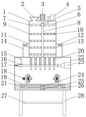
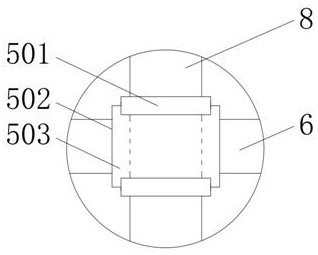
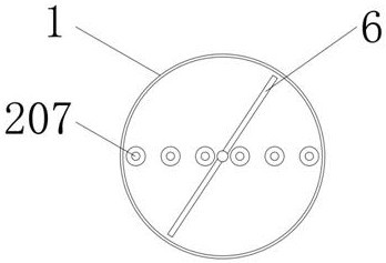
The invention belongs to the related technical field of sand blasting machines, and particularly relates to a sand blasting machine. The sand blasting machine comprises a stirring box and a spraying box, and is characterized in that a feeding opening is formed in the left side of the upper portion of the stirring box, a first motor is fixed to the central position of the upper portion of the stirring box, and an air compressor is arranged on the right side of the upper portion of the stirring box; discharging mechanisms are arranged at the middle position of the upper wall of the interior of the spraying box, a second telescopic air cylinder is fixedly connected to the inner wall of the right side of the spraying box, and the output end of the second telescopic air cylinder is fixedly connected with the right end of a connecting plate; and a second sliding frame is fixedly connected to the lower portion of the inner wall of the spraying box, and the second sliding frame is slidably connected with a fixing mechanism. Through the design of the fixing device, workpieces of different sizes can be clamped and fixed, the workpieces can be clamped from the outer sides of the workpieces and can also be clamped from the interiors of the workpieces, and it is guaranteed that the outer surfaces of the workpieces are sprayed without dead corners.

Description

technical field [0001] The invention relates to the related technical field of sandblasting machines, in particular to a sandblasting machine. Background technique [0002] The sandblasting machine uses compressed air to transport the powdery particles (1~4mm in diameter) from one place to another in the pipeline, and in the process of converting kinetic energy into potential energy, the high-speed moving sand scours the surface of the object. The impact and cutting effect of sand on the surface of the workpiece makes the surface of the workpiece obtain a certain degree of cleanliness and different roughness, which improves the mechanical properties of the surface of the workpiece, thus improving the fatigue resistance of the workpiece and increasing the distance between it and the coating. The adhesion between them prolongs the durability of the coating film, and it is also beneficial to the leveling and decoration of the coating. It removes impurities, variegated colors an...

Claims


Application Information

Patent Timeline
Patent Type & Authority Applications(China)
IPC IPC(8): B24C1/08B24C3/04B24C9/00B24C5/04B05B13/04B05B13/02B05B15/20F16F15/067
CPCB05B13/0285B05B13/041B24C1/08B24C3/04B24C5/04B24C9/00B05B15/20F16F15/067
Inventor 不公告发明人
Owner 邹连美
Learn More