Light-emitting equipment

A technology for light-emitting equipment and light sources, which is applied to lighting and heating equipment, optical elements for changing the spectral characteristics of emitted light, lighting devices, etc. Poor light effect, etc.

Pending Publication Date: 2021-05-18
万民
View PDF0 Cites 1 Cited by
  • Summary
  • Abstract
  • Description
  • Claims
  • Application Information

AI Technical Summary

Problems solved by technology

[0012] The technical problems to be solved by the present invention are: first) the light mixing effect of the outgoing light of the existing light-emitting devices using dichroic mirrors is not good; In the process, the output of luminous flux will be affected; third) the color rendering index of the outgoing

Method used


Image

  • Light-emitting equipment
  • Light-emitting equipment
  • Light-emitting equipment

Examples


Embodiment 1

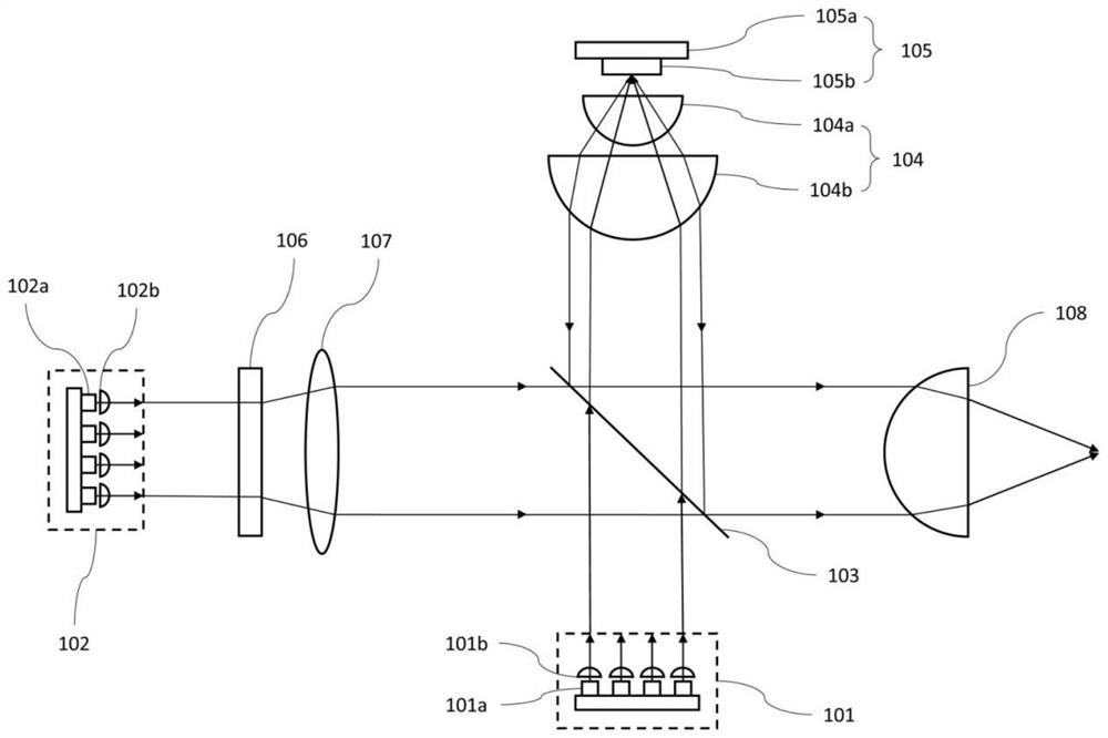
[0158] Such as Image 6 As shown, a light emitting device disclosed in this embodiment includes a first light source 601, a second light source 602, a dichroic mirror 603, a first collection optical system, a wavelength conversion device 605, a first optical path adjustment device, a polarization conversion element, The second collecting optical system, the first scattering optical system and the light collecting optical system. The first light source 601 includes several lasers 601a and several collimating lenses 601b corresponding to the several lasers 601a one by one, wherein the lasers 601a emit blue light with a dominant wavelength of 455nm. The second light source 602 includes a number of lasers 602a and a number of collimator lenses 602b corresponding to the number of lasers 602a, wherein the laser 602a emits blue light with a dominant wavelength of 455nm. The first collection optical system consists of a lens group 604 including a lens 604a and a lens 604b. The wavel...

Embodiment 2

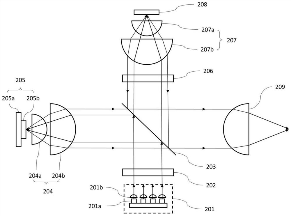
[0163] Such as Figure 7 As shown, a light emitting device disclosed in this embodiment includes a first light source 701 (consisting of several lasers 701a and several collimating lenses 701b corresponding to the several lasers 701a), a second light source 702 (consisting of several lasers 701a) Laser 702a and several collimating lenses 702b corresponding to several lasers 702a), dichroic mirror 703, first collection optical system (consisting of lens group 704 including lens 704a and lens 704b), wavelength conversion device 705 (comprising a reflective layer 705a and a wavelength conversion layer 705b disposed on the reflective layer 705a), the first optical path adjustment device (composed of a flat-plate polarization beam splitter 706), polarization conversion element (composed of a quarter-wave plate 707 Composition), the second collecting optical system (consisting of lens group 708 including lens 708a and lens 708b), the first scattering optical system (consisting of a ...

Embodiment 3

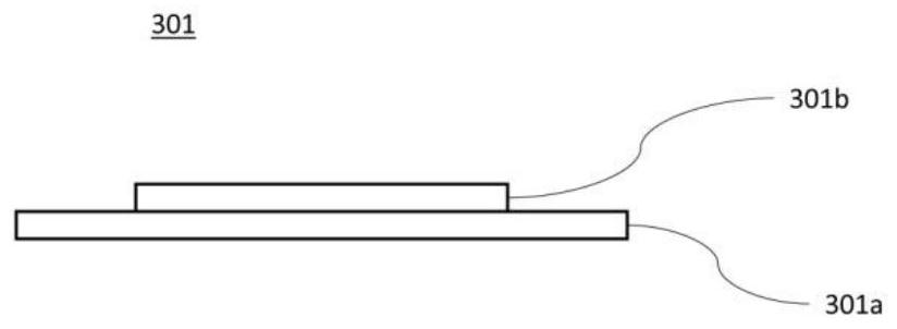
[0167] Such as Figure 8 As shown, a light emitting device disclosed in this embodiment includes a first light source 801 (consisting of several lasers 801a and several collimating lenses 801b corresponding to the several lasers 801a), a second light source 802 (consisting of several lasers 801a) Laser 802a and several collimating lenses 802b corresponding to several lasers 802a), dichroic mirror 803, first collection optical system (consisting of lens group 804 including lens 804a and lens 804b), wavelength conversion device 805 (comprising a reflective layer 805a and a wavelength conversion layer 805b disposed on the reflective layer 805a), a first optical path adjustment device, a polarization conversion element (composed of a quarter-wave plate 807), a second collection optical system (composed of The lens group 808 of lens 808a and lens 808b is constituted), the first diffuse optical system (constituted by a reflective diffuser plate 809), the converging optical system (c...


PUM


Abstract

The invention provides light-emitting equipment. The light-emitting equipment comprises a first light source, a second light source, a dichroscope, a wavelength conversion device, a first light path adjusting device or a second light path adjusting device and a first scattering optical system. According to the light-emitting equipment, the light mixing effect of the emergent light can be improved by the aid of the first scattering optical system. The color temperature of the emergent light of the light-emitting equipment can be freely adjusted by independently adjusting the power of the first light source and the second light source. A laser capable of emitting light of different dominant wavelengths can be used in the first light source to improve the color rendering index of emergent light of the light-emitting equipment. The light emitted by the second light source is completely used for exciting the wavelength conversion device, compared with the prior art, the light-emitting equipment can achieve output with higher luminous flux under the condition that the optical expansion amount is not increased, and if a polarization selection element is used in the second light source in a matched mode, the output luminous flux of the light-emitting equipment can be further improved.

Description

technical field [0001] The invention belongs to the field of lighting, in particular to the field of solid-state light source lighting. The light-emitting device provided by the present invention can be applied to systems that require high light intensity and small etendue, such as entertainment lighting systems, projection systems, automotive lighting systems, medical lighting systems, search lighting systems, field operation lighting systems, Nautical lighting systems, portable lighting systems, etc. Background technique [0002] As an ideal point light source, the laser has the advantages of small etendue, long life and mercury-free. It is used as a light source to excite fluorescent materials to obtain colored light or white light. Etendue luminaire. [0003] figure 1 is a structural schematic diagram of an existing light-emitting device using a dichroic mirror. Such as figure 1 As shown, the existing light-emitting device using a dichroic mirror includes a light so...

Claims


Application Information

Patent Timeline
IPC IPC(8): F21V9/32F21V9/38F21V9/20F21V9/14
CPCF21V9/32F21V9/38F21V9/20F21V9/14
Inventor 万民
Owner 万民
Why Eureka
Try Eureka