
Waste gas conveying and treating device for environmental protection equipment

A technology of environmental protection equipment and processing devices, applied in gas treatment, lighting and heating equipment, air quality improvement, etc., can solve the problems of increasing exhaust gas pollution, inconvenient work, incompleteness, etc.

Pending Publication Date: 2021-05-18
苏州市亿兆机电工程技术有限公司
View PDF6 Cites 0 Cited by
  • Summary
  • Abstract
  • Description
  • Claims
  • Application Information

AI Technical Summary

Problems solved by technology

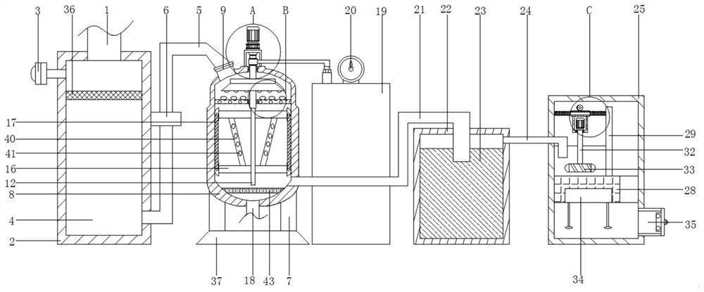
[0002] Environmental protection equipment refers to mechanical products, structures and systems manufactured and built by production units or construction installation units for controlling environmental pollution and improving environmental quality. Some people think that environmental protection equipment refers to mechanically processed products that control environmental pollution , Honeycomb activated carbon such as dust collectors, welding fume purifiers, monomer water treatment equipment, noise controllers, etc. This understanding is not comprehensive. Environmental protection equipment should also include power equipment that transports fluid substances containing pollutants, such as water pumps, Fans, conveyors, etc.; also include monitoring and control instruments to ensure the normal operation of pollution prevention and control facilities, such as testing instruments, pressure gauges, flow monitoring devices, etc., because most of the existing environmental protection equipment does not have good waste gas treatment capabilities, resulting in Its internal air purification ability is poor, which increases the situation that there are still many harmful substances after waste gas treatment, and cannot effectively ensure that the waste gas can be directly discharged into the atmosphere after purification treatment, which increases the situation of waste gas polluting the air, which is harmful to the staff. The work has brought inconvenience and brought some adverse effects to the actual use, so it needs to be improved

Method used


Image

  • Waste gas conveying and treating device for environmental protection equipment
  • Waste gas conveying and treating device for environmental protection equipment
  • Waste gas conveying and treating device for environmental protection equipment

Examples


Embodiment Construction

[0022] The following will clearly and completely describe the technical solutions in the embodiments of the present invention with reference to the accompanying drawings in the embodiments of the present invention. Obviously, the described embodiments are only some, not all, embodiments of the present invention. Based on the embodiments of the present invention, all other embodiments obtained by persons of ordinary skill in the art without making creative efforts belong to the protection scope of the present invention.

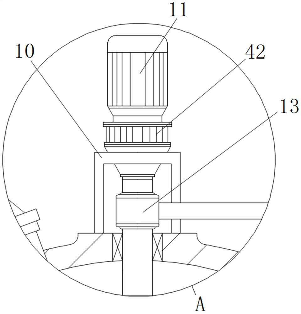
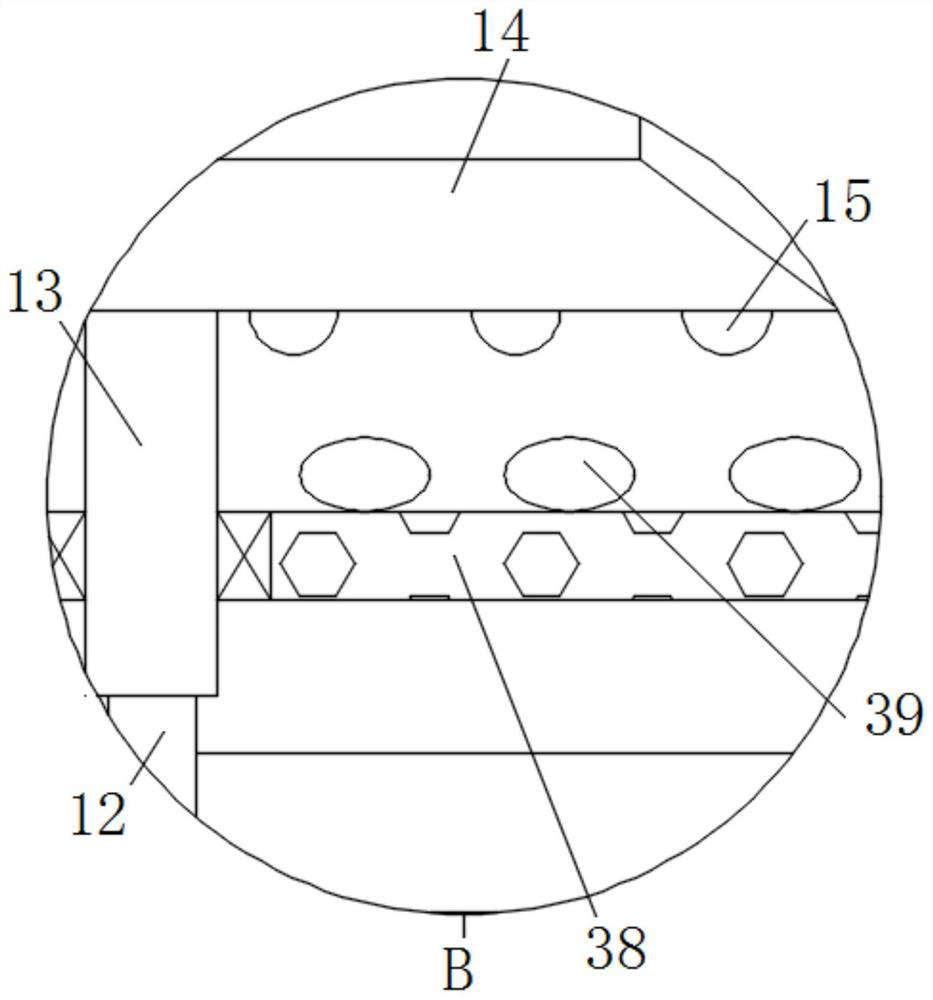
[0023] see Figure 1 to Figure 6 , the present invention provides a technical solution: a waste gas conveying and processing device for environmental protection equipment, including a waste gas discharge pipe 1, the waste gas inside the waste gas discharge pipe 1 can enter the inside of the heating combustion box 2, and the bottom end of the waste gas discharge pipe 1 is fixedly connected There is a heating combustion box 2, the inside of the heating combustio...


PUM


Abstract

The invention disclose a waste gas conveying and treating device for environmental protection equipment. The device comprises a waste gas discharging pipe, the bottom end of the waste gas discharging pipe is fixedly connected with a heating combustion box, the left side of the heating combustion box is fixedly connected with a gas conveying pipe, the interior of the heating combustion box is filled with combustible gas, a guide pipe is fixedly connected to the side face, close to the bottom, of the heating combustion box, a stabilizing plate is fixedly connected to the side face of the guide pipe, and the side face of the stabilizing plate is fixedly connected with the side face of the heating combustion box. According to the device, through cooperation of the structures, the air purification capacity of the environment protection equipment is improved, the situation that many harmful substances still exist after waste gas treatment is reduced, the cleaning work of impurities in waste gas is accelerated, it is guaranteed that the waste gas can be directly discharged into the atmosphere after purification treatment, the situation that air is polluted by the waste gas is reduced, and convenience is brought to the work of workers.

Description

technical field [0001] The invention relates to the technical field of waste gas treatment devices, in particular to a waste gas transport and treatment device for environmental protection equipment. Background technique [0002] Environmental protection equipment refers to mechanical products, structures and systems manufactured and built by production units or construction installation units for controlling environmental pollution and improving environmental quality. Some people think that environmental protection equipment refers to mechanically processed products that control environmental pollution , Honeycomb activated carbon such as dust collectors, welding fume purifiers, monomer water treatment equipment, noise controllers, etc. This understanding is not comprehensive. Environmental protection equipment should also include power equipment that transports fluid substances containing pollutants, such as water pumps, Fans, conveyors, etc.; also include monitoring and c...

Claims


Application Information

Patent Timeline
IPC IPC(8): F23G7/06B01D53/18B01D53/04B01D53/32B01D53/75B01D53/84B08B9/087
CPCF23G7/065B01D53/185B01D53/04B01D53/007B01D53/32B01D53/75B01D53/84B08B9/087B01D2257/90B01D2257/91B01D2259/818Y02A50/20
Inventor 刘天刚周长东
Owner 苏州市亿兆机电工程技术有限公司
Learn More