Self-steady flow type energy storage pool

An accumulator and flow-type technology, which is applied in the field of self-stabilizing flow-type accumulators, can solve the problems of huge cost, large floor area, and inapplicability of large-scale accumulators.

Active Publication Date: 2021-05-18
华春新能源股份有限公司
View PDF7 Cites 0 Cited by
  • Summary
  • Abstract
  • Description
  • Claims
  • Application Information

AI Technical Summary

Problems solved by technology

Although this solution can realize the absolute isolation of cold water and hot water, it is not suitable for large storage tanks.
At present, some energy storage pools are installed in the basement or roof of the building, directly using the area of ​​the basement or roof, and occupy a huge area. It is difficult to set up a structure that can slide up and down such a large partition. Even if it is realized, It will also be very expensive

Method used


Image

  • Self-steady flow type energy storage pool
  • Self-steady flow type energy storage pool
  • Self-steady flow type energy storage pool

Examples


Embodiment Construction

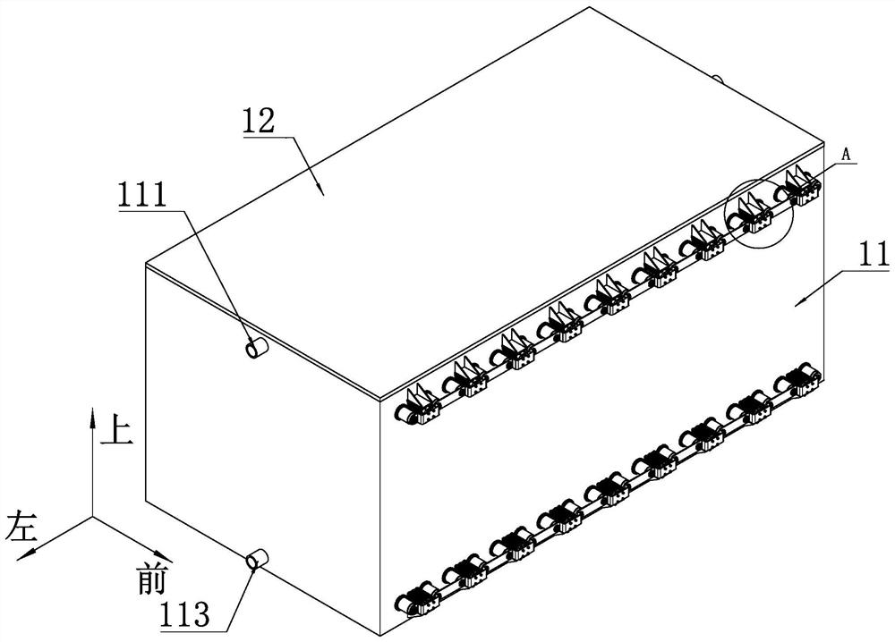
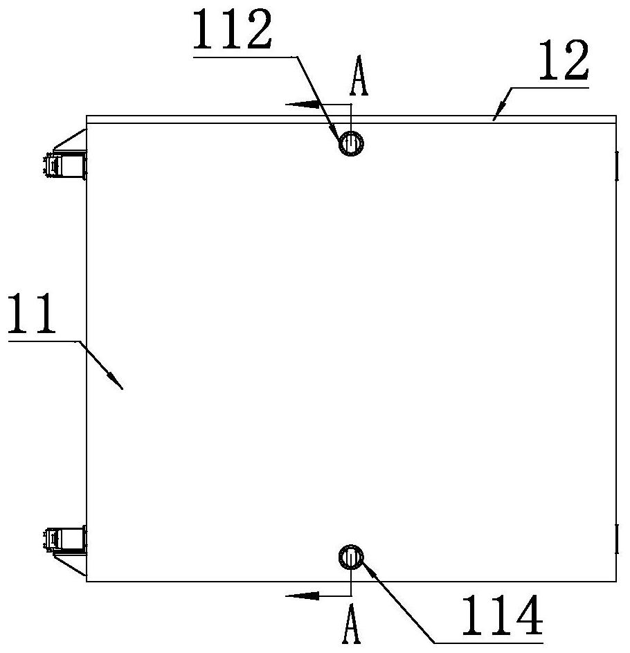
[0054] For the convenience of description, the coordinate system is defined as figure 1, and the left-right direction is horizontal, the front-back direction is vertical, and the up-down direction is vertical. In the embodiment, cold storage is taken as an example. The flow direction of the inlet and outlet pipes during heat storage is opposite to that of the cold storage type, and the other embodiments are the same.

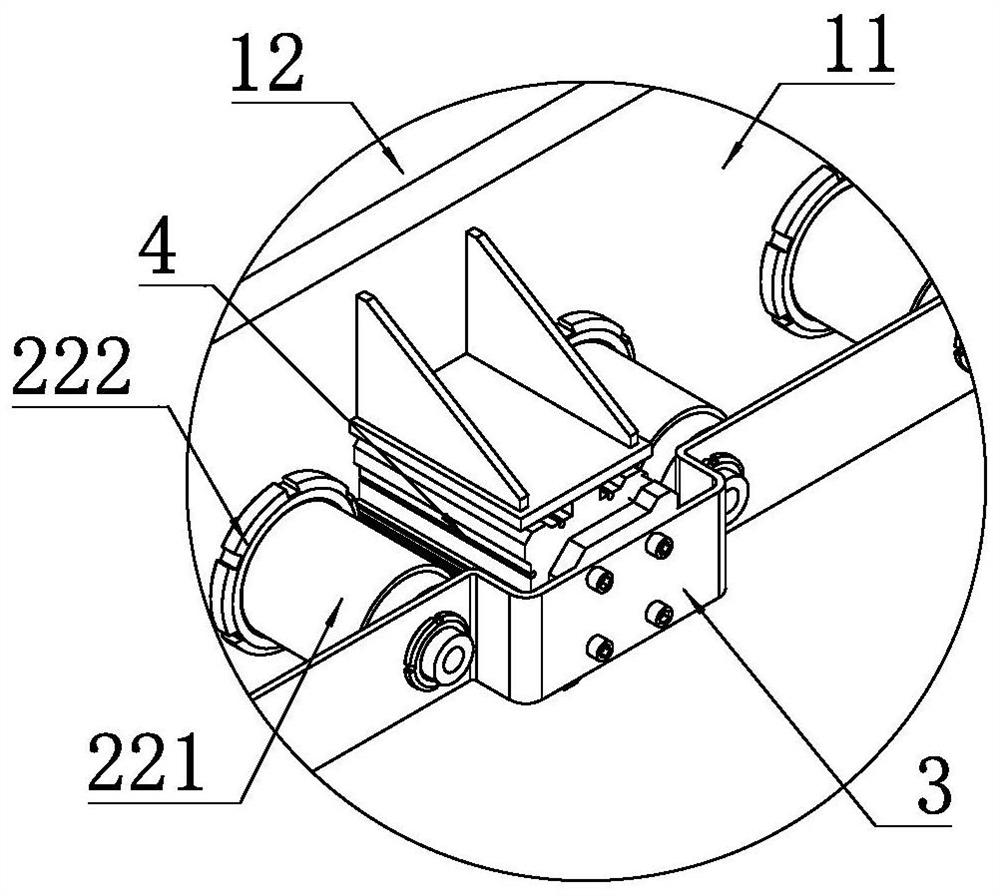
[0055] Such as figure 1 , image 3 with Figure 4 As shown, a self-stabilizing flow type accumulator includes a main box body 11 with heat preservation function and an upper cover plate 12, the upper cover plate 12 is sealed and fixedly connected with the box body by bolts, and the box body The body and the upper cover plate 12 jointly form a hollow cuboid box. Two water distributors are arranged symmetrically in the box, and the water distributor divides the inner space of the box into three spaces that are not connected to each other. energy zone and cold...


PUM


Abstract

The invention discloses a self-steady flow type energy storage pool, and relates to the technical field of energy storage equipment. The self-steady flow type energy storage pool specifically comprises a box body, wherein two water distributors are symmetrically arranged in the box body, and the water distributors sequentially divide the inner space of the box body into a hot water transition area, an energy storage area and a cold water transition area which are not communicated with one another from top to bottom. Each water distributor comprises fixed partition plates and water distribution assemblies which are arranged at intervals, each water distribution assembly comprises a water distribution barrel, and a plurality of first flow channels and second flow channels which are arranged at intervals are evenly distributed on each water distribution barrel in the axis direction. A valve core is arranged in each water distribution barrel, each valve core comprises a piston part and a connecting rod part which are arranged at an interval, an air passage is arranged in each valve core, an air bag sleeves outside each connecting rod part, and the position, positioned in the corresponding air bag, of each connecting rod part is provided with an air hole communicated with the corresponding air passage. One-way valves are arranged on first water filling pipes, first water discharging pipes, second water filling pipes and second water discharging pipes. The energy storage pool can reduce the thickness of a thermocline and ensure the stability of the thermocline.

Description

technical field [0001] The invention relates to the technical field of energy storage equipment, in particular to a self-stabilizing flow energy storage pool. Background technique [0002] The main principle of the water storage air-conditioning system is to store cold water in the cold storage device during the low power consumption period, and release the stored cold water for use during the peak power consumption period, so as to achieve the purpose of "shifting the peak and filling the valley". The heat pump system works on the same principle as water heat storage. [0003] The performance of water energy storage air conditioning or heat pump system is largely affected by water energy storage technology. The so-called water energy storage technology is to use the phenomenon that the density of water is different at different temperatures. Above, the low-temperature water is below, thus realizing the technology of natural stratification of cold water and hot water. The ...

Claims


Application Information

Patent Timeline
IPC IPC(8): F24F5/00F24F13/00
CPCF24F5/0017F24F13/00Y02E60/14
Inventor 张庆红平杰刘彦德江宾
Owner 华春新能源股份有限公司
Why Eureka
Try Eureka