[0020] It should be noted that, in the case of no conflict, the embodiments in the present application and the features in the embodiments can be combined with each other. The present invention will be described in detail below with reference to the accompanying drawings and examples.
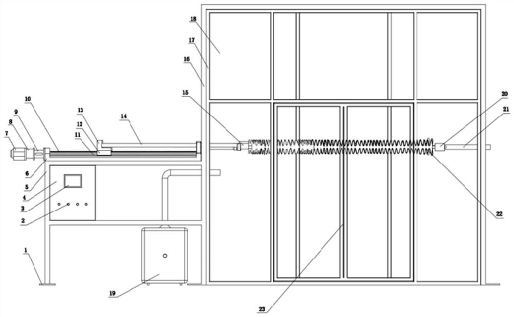
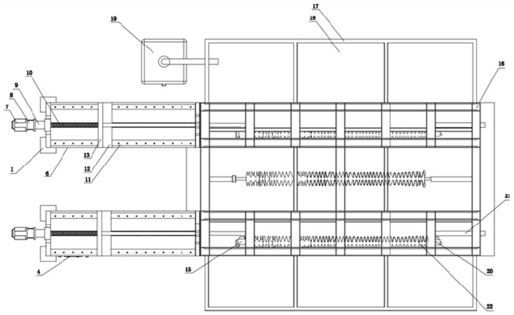
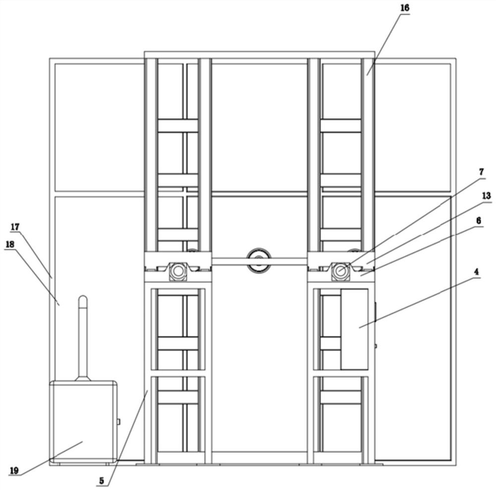
[0021] like Figure 1 to Figure 3 As shown, the embodiment of the present invention provides a bending fatigue device for insulators, including a fog chamber 16, a fogging controller 19, a first connection component, a second connection component, a test composite insulator 22 and a bending application component. The mist chamber 16 has an inner chamber, and the fogging controller 19 is disposed outside the mist chamber 16 and communicated with the inner chamber. The first connection assembly and the second connection assembly are symmetrically arranged on two opposite side walls of the mist chamber 16, one end of the first connection assembly is placed in the mist chamber 16, and the other end of the first connection assembly is placed outside the mist chamber 16, One end of the second connection assembly is placed in the mist chamber 16 , and the other end of the second connection assembly is connected to the corresponding side wall of the mist chamber 16 . A trial composite insulator 22 is connected between one end of the first connection assembly and one end of the second connection assembly. The bending applying component is drivingly connected to the other end of the first connecting component.
[0022] Installing the test composite insulator 22 in the fog chamber 16 can simulate the analysis of the bending fatigue strength of the insulator in a windy and foggy environment under operating conditions, thereby providing a basis for the selection of the insulator.
[0023] Preferably, the bending fatigue equipment of the insulator in the embodiment of the present invention further includes a power supply assembly (not shown), which is arranged above the fog chamber 16 and connected to both ends of the test composite insulator 22 through wires. During operation, a high-voltage environment is provided for both ends of the test composite insulator 22 through the power supply component, so as to simulate the fatigue strength analysis of the insulator under the high-voltage environment in windy and foggy conditions during energized operation.
[0024] The first connection assembly in the embodiment of the present invention includes a curved top shaft 14 and a front end angle adjustment device 15 , one end of the curved top shaft 14 is connected to the bending application assembly, and the other end of the curved top shaft 14 is connected to the front end angle adjustment device 15 . The front end angle adjusting device 15 is arranged in the mist chamber 16 . The second connection assembly includes an adjustment shaft 21 and a rear end angle adjustment device 20, one end of the adjustment shaft 21 is connected to the corresponding side wall of the mist chamber 16, and the other end of the adjustment shaft 21 is connected to the rear end angle adjustment device 20, and the rear end angle adjustment The device 20 is set in the mist chamber 16, and the two ends of the test composite insulator 22 are respectively connected to the front end angle adjustment device 15 and the rear end angle adjustment device 20.
[0025] The front end angle adjustment device 15 and the rear end angle adjustment device 20 in the embodiment of the present invention can independently follow the test composite insulator 22 to rotate upwards and downwards, the adjustment shaft 21 can adjust the installation position according to the length of the insulator, and the bending top shaft 14 is a rigid straight bar.
[0026] like figure 1 and figure 2 As shown, the bending applying assembly in the embodiment of the present invention includes a slide plate seat 6, a rotating screw 10, two linear guide rails 11, a motor assembly and a slider assembly. The slide plate seat 6 is arranged outside the mist chamber 16 . The rotating screw mandrel 10 is rotatably arranged on the slide plate seat 6 . Two linear guide rails 11 are fixedly arranged on the slide plate seat 6 , and the two linear guide rails 11 are parallel and symmetrically arranged on both sides of the rotating screw rod 10 . The motor assembly is arranged at one end of the slide plate seat 6 and is drivenly connected with one end of the rotating screw mandrel 10 . The slider assembly is slidably arranged on the two linear guide rails 11, and the lower end of the slider assembly is connected with the rotating screw 10, and the upper end of the slider assembly is connected with one end of the first connecting assembly.
[0027] The motor assembly can drive the rotating screw 10 to rotate, so that the slider assembly slides relative to the slide plate seat 6, and stress is applied to one end of the first connecting assembly to simulate the actual working conditions of the composite insulator 22 in a windy day test. In this embodiment The slider assembly can apply compression or tension, or alternate compression and tension, to provide the most realistic simulated conditions for real operating conditions.
[0028] Specifically, the motor assembly includes a coupling support 9 , a reducer 8 and a servo motor 7 . The shaft coupling support 9 is arranged on one end of the slide plate seat 6 and is connected with one end of the rotating screw mandrel 10 . The speed reducer 8 is arranged on the end of the coupling support 9 away from the slide plate seat 6 , the speed reducer 8 is connected with the shaft coupling in the coupling support 9 , and then connected with the rotating screw 10 . The drive shaft of the servo motor 7 is connected to the input shaft of the speed reducer 8 .
[0029] In the embodiment of the present invention, precise stress can be applied at a set time by setting the reducer 8 and the servo motor 7, so as to achieve the purpose of accurate simulation.
[0030] Preferably, the slider assembly includes a guide rail slider 12 and a slider seat 13, the guide rail slider 12 can be slidably arranged on two linear guide rails 11, and the guide rail slider 12 is connected with the rotating screw mandrel 10; the slider seat 13 is fixed On the guide rail slider 12 and capable of moving with the guide rail slider 12 , the slider seat 13 is connected to one end of the first connecting assembly. The guide rail slider 12 has the same structure as the slider in the prior art, and its specific shape and installation method will not be repeated here. The slider seat 13 is a plate-shaped structure whose lower end is fixed on the guide rail slider 12, and one side of its upper end is fixedly connected with one end of the first connection assembly to drive the first connection assembly to apply tension or pressure. At the same time, the slider seat 13 The thickness can be selected according to different needs.
[0031] like Figure 1 to Figure 3 As shown, the bending fatigue equipment for insulators in the embodiment of the present invention also includes a curved platform support 5 with an inner space, a slide plate seat 6 is fixedly arranged on the curved platform support 5, and a fogging controller 19 is arranged in the inner space. The curved platform support 5 is arranged on one side of the mist chamber 16 .
[0032] The fogging controller 19 is arranged in the inner space, that is, relative to the fogging chamber 16, the fogging controller 19 and the bending application assembly are located on the same side of the fogging chamber 16, which is convenient for staff to adjust. The fogging controller 19 in this embodiment can manually or automatically adjust the amount of fog.
[0033] Preferably, the bending fatigue equipment for insulators further includes a control cabinet 4 which is arranged on the bending platform support 5 and connected with the motor assembly. The control cabinet 4 is provided with a touch controller 3 and control buttons 2 . The control cabinet 4 can control various parameters of the bending applying assembly to adjust the stress of the bending applying assembly on the test composite insulator 22 .
[0034] It should be noted that the lower part of the curved platform support 5 is connected to the support platform through the fixed bottom plate 1, so that the support of the curved platform support 5 is more stable.
[0035] like figure 2 As shown, the first connection component, the second connection component, the test composite insulator 22 and the bending application component constitute a set of bending fatigue components, and the bending fatigue equipment of the insulator includes at least two groups of bending fatigue components arranged in parallel and symmetrically.
[0036] In the embodiment of the present invention, at least two sets of parallel and symmetrically arranged bending fatigue components can be used to perform bending fatigue tests at different angles on two sets of test composite insulators 22 at the same time, which improves the experimental efficiency of the overall device. At the same time, at least two sets of parallel and symmetrically arranged bending fatigue components Components can be compared with each other to achieve the purpose of providing basis for the selection of insulators.
[0037] Preferably, the bending fatigue equipment of the insulator also includes a group of control components, which are arranged in parallel with the bending fatigue components. The control components include the test composite insulator 22 and the fixed shaft. side wall connections. The installation position of the fixed shaft can be adjusted according to the length of the test composite insulator 22 . In this embodiment, a set of control components can be provided to better compare with at least two sets of parallel and symmetrical bending fatigue components.
[0038] It should be noted that the control cabinet 4 can respectively control the bending at different speeds and angles of at least two groups of bending fatigue components arranged in parallel and symmetrically.
[0039] like Figure 1 to Figure 3 As shown, the mist chamber 16 in the embodiment of the present invention adopts an all-aluminum alloy frame. The front of the mist chamber 16 is provided with a side-by-side door 23. The main frame of the side-by-side door 23 is composed of a main profile 17 and an acrylic plate 18. The board can facilitate the staff to observe the situation in the mist chamber 16 from the outside.
[0040] From the above description, it can be seen that the above-mentioned embodiments of the present invention have achieved the following technical effects: it is possible to carry out a composite insulator decay defect simulation test considering moisture, electric field, and mechanical bending factors, and the test composite insulator is installed in a fog chamber Applying voltage, simulating fatigue strength analysis of test composite insulators in windy, foggy and high-voltage environments under operating conditions, considering moisture, electric field, and mechanical bending factors, so as to provide a basis for insulator type selection.
[0041] The above is only a specific embodiment of the present invention, and cannot limit the scope of the invention, so the replacement of its equivalent components, or the equivalent changes and modifications made according to the patent protection scope of the present invention, should still fall within the scope of this patent. category. In addition, the technical features and technical features, technical features and technical solutions, and technical solutions and technical solutions in the present invention can be used in free combination.