Gas dilution device and method based on selection technology

A selection technology and dilution device technology, which is applied in the field of gas dilution devices based on selection technology, can solve the problem of not being able to selectively prepare different concentrations of various species, failing to meet the monitoring requirements of the ozone layer depleting substance system, and being unable to prepare ppt-level concentration standard gas, etc. question

Pending Publication Date: 2021-05-18
HANGZHOU PUYU TECH DEV CO LTD
View PDF14 Cites 1 Cited by
  • Summary
  • Abstract
  • Description
  • Claims
  • Application Information

AI Technical Summary

Problems solved by technology

[0004] 1. The concentration of a single gas distribution is single, and different concentrations of various species cannot be selectively prepared according to actual needs;
[0005] 2. It needs to consume a large flow of dilution gas for dilution, and the consumption of standard gas is large;
[0006] 3. The dilution ratio is limited and cannot b

Method used


Image

  • Gas dilution device and method based on selection technology

Examples


Embodiment 1

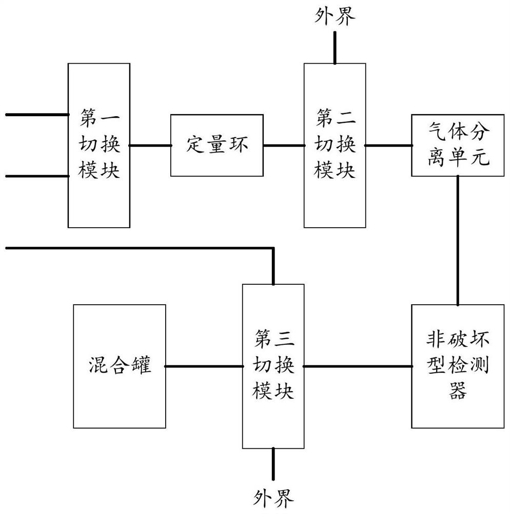
[0034] figure 1 A schematic diagram of the structure of the gas dilution device based on the selection technology of the embodiment of the present invention is given, as figure 1 As shown, the gas dilution device based on selected technology includes:

[0035] mixing tank;

[0036] A first switching module, such as a multi-way valve or a combination of multiple two-way valves, the first switching module is used to selectively connect the input end of the quantitative loop to the first gas and the second gas;

[0037] Quantitative loop and gas separation unit;

[0038] A second switching module, the second switching module is used to selectively connect the output end of the quantitative loop to the gas separation unit or the outside world;

[0039] A non-destructive detector, such as a PID detector, the input end of the non-destructive detector is connected to the gas separation unit, and the output end is connected to the third switching module;

[0040] A third switching...

Embodiment 2

[0055] An application example of the gas dilution device based on selection technology according to Embodiment 1 of the present invention.

[0056] In this application example, the first switching module uses a two-position three-way valve, the second switching module and the third switching module use a four-way valve; the first gas is the standard gas, the second gas is the carrier gas (diluent gas), and the second The three gases and the second gas are shared; the first gas and the second gas are connected to the first switching module, and the second gas is also connected to the third switching module through a gas pipeline; the gas separation unit adopts a chromatographic column, and the non-destructive detector adopts a PID Detector; mixing tank adopts Suma tank.

[0057] The gas dilution method based on the selected technology of the present embodiment comprises the following steps:

[0058] The first switching module and the second switching module are switched, and the...


PUM


Abstract

The invention provides a gas dilution device and method based on a selection technology. The gas dilution device based on the selection technology comprises a mixing tank, a quantitative ring and a gas separation unit, wherein the first switching module is used for enabling the input end of the quantitative ring to selectively communicate with first gas and second gas; the second switching module is used for enabling the output end of the quantitative ring to selectively communicate with the gas separation unit or the outside; the input end of a non-destructive detector is connected with the gas separation unit, and the output end of the non-destructive detector is connected with a third switching module; the third switching module is used for enabling the outlet of the non-destructive detector to be selectively connected with the mixing tank and the outside; third gas enters the mixing tank through a gas pipeline; and a metering module is used for metering the third gas. The gas dilution device meets the requirement of trace gas dilution.

Description

technical field [0001] The present invention relates to gas dilution, in particular to a gas dilution device and method based on selection technology. Background technique [0002] The concentration of ozone depleting substances in the ambient air is extremely low and relatively stable, usually on the order of 1ppt-1ppb, and the concentration of some components is on the order of 0.1ppt. In the field of environmental monitoring in our country, there is a lack of systematic analysis and monitoring methods and scientific quality control methods. Among them, the key to quality control is the standard gas preparation for such trace concentrations of ozone layer depleting substances. The quality control of such substances is different from the conventional method of monitoring volatile organic compounds in the ambient air. It needs to prepare the corresponding concentration according to the actual concentration of each substance in the ambient air to ensure the accuracy and effe...

Claims


Application Information

Patent Timeline
IPC IPC(8): G01N30/06G01N30/02G01N30/86
CPCG01N30/06G01N30/02G01N30/8675
Inventor 王鹏侯生贤刘盈智刘立鹏韩双来黄俊兴
Owner HANGZHOU PUYU TECH DEV CO LTD
Why Eureka
Try Eureka