A thermocirculator

A thermal cycle device, cooling device technology, applied in the direction of biochemical cleaning device, enzymology/microbiology device, heating or cooling equipment, etc., to reduce heat transfer and improve accuracy

Inactive Publication Date: 2021-05-25
RWD LIFE SCI
View PDF9 Cites 1 Cited by
  • Summary
  • Abstract
  • Description
  • Claims
  • Application Information

AI Technical Summary

Problems solved by technology

[0005] The embodiment of the present invention provides a thermal cycle device, which aims to solve the problems of the accuracy of the temperature control of each part of the sample block and the repeatability of the experiment in the prior art

Method used


Image

  • A thermocirculator
  • A thermocirculator
  • A thermocirculator

Examples


Embodiment 1

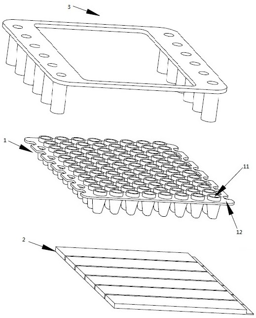
[0024] figure 1 It is an exploded view of the thermal cycle device provided in Embodiment 1 of the present invention. Such as figure 1 As shown, the thermal cycle device includes a sample block 1 and N heating and cooling devices 2 .

[0025] In the embodiment of the present invention, the sample block 1 is provided with blind holes 11 arranged at uniform intervals to form a blind hole array. Blind holes 11 refer to the hole slots on the sample block 1 where PCR tubes can be placed. In the blind hole array, and the inner wall of the blind hole 11 is as close as possible to the outer wall of the tube of the PCR plate, which is beneficial to heat conduction. Biological samples are substances that need to undergo thermal cycle reactions, including but not limited to oligonucleotides used as primers, dNTP mixtures, Taq DNA polymerase, and PCR buffers. The upper parts of all blind holes 11 are connected. The connection part should be as close as possible to the opening of the ...

Embodiment 2

[0034] In this embodiment of the present invention, the basic structure of the thermal cycle device is the same as that of Embodiment 1, and the same components as in Embodiment 1 continue to use the same symbols as in Embodiment 1, including all the features described in Embodiment 1, which are not described herein. Let me repeat.

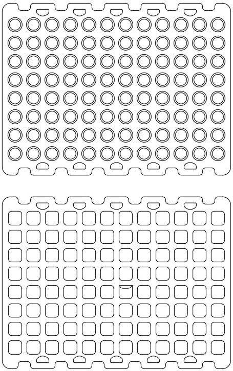
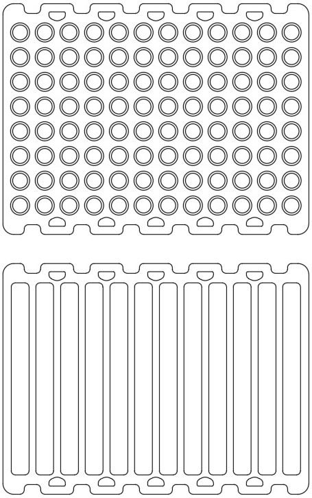
[0035] Figure 6 It is an exploded diagram of the thermal cycle device provided by the second embodiment of the present invention. Figure 7 It is a top view of the sample block provided by Embodiment 2 of the present invention. combine Figure 6 and Figure 7 , the thermal cycling device includes a sample block 1 , N heating and cooling devices 2 , and a pressing member 3 . The sample block 1 also includes an array of through holes arranged in the upper connected plane of the blind holes 11 . Through-holes 13 are provided between the connecting portion on the upper part of the blind holes 11 and the blind holes 11 . In the embodiment of the...

Embodiment 3

[0039] In this embodiment of the present invention, the basic structure of the thermal cycle device is the same as that of Embodiment 1 or Embodiment 2, and the components that are the same as Embodiment 1 or Embodiment 2 continue to use the same symbols, including all the features described therein, and are not described here. Let me repeat.

[0040] Figure 8 It is an exploded view of the thermal cycle device provided by Embodiment 3 of the present invention. Figure 9 It is a schematic diagram of the thermal cycle device provided in Embodiment 3 of the present invention. combine Figure 8 and Figure 9 , the thermal cycling device includes a sample block 1, N heating and cooling devices 2, a pressing member 3, a first heat conducting element 5, a TEC spacer 6, a second heat conducting element 7, a heat sink 8, a heat cover 9 and a bottom case 10 .

[0041] The bottom case 10 is used to bear all the weight of the thermal cycler. The heat sink 8 is fixed in the bottom c...


PUM


Abstract

The embodiment of the invention provides a thermocirculator. The thermocirculator comprises a sample block (1) provided with a blind hole array; and N heating and cooling means (2), N being a positive integer greater than 2; wherein the upper parts of all the blind holes (11) are connected, the N heating and cooling devices (2) respectively heat and/or cool the bottoms of the blind holes (11) in N different areas of the sample block (1), and each area comprises one or more blind holes (11). According to the embodiment of the invention, the upper parts of the blind holes in the sample block are connected, and the bottoms of the blind holes in different areas of the sample block are respectively heated and/or cooled through the N heating and cooling devices, so that the heat transfer effect among the blind holes in different areas of the sample block is reduced; and the accuracy of temperature control of different areas of the sample block and the repeatability of the experiment are improved.

Description

technical field [0001] The invention relates to the technical field of reaction vessels for performing chemical reactions or biological reactions, in particular to a heat cycle device. Background technique [0002] In the process of exploring the optimal reaction temperature and optimal reaction time of biological samples or chemical samples, it is often necessary to set and execute a series of temperature cycles for biological samples or chemical samples, and select the best combination of temperature and time. [0003] In the prior art, devices that perform the above series of temperature cycles include polymerase chain reaction (PCR, Polymerase chain reaction) nucleic acid amplification instruments, which can also be called PCR instruments and thermal cycle devices. The thermal cycle device comprises a sample block uniformly provided with an array of blind holes, and a heating device and a cooling device are arranged under opposite sides of the sample block. Put the PCR ...

Claims


Application Information

Patent Timeline
Patent Type & Authority Applications(China)
IPC IPC(8): B01L7/00C12M1/38C12M1/02
CPCB01L7/52
Inventor 李晓东阳方义
Owner RWD LIFE SCI
Why Eureka
Try Eureka