Magnetic type clamp for electric spark machining

A kind of electric spark and magnetic suction technology, applied in electric processing equipment, manufacturing tools, metal processing equipment and other directions, can solve the problems of inconvenient clamping and positioning, affecting processing, different workpiece shapes, etc., to achieve good clamping effect, The effect of avoiding limitations and simple and convenient operation

Inactive Publication Date: 2021-05-25
张晓民
View PDF0 Cites 0 Cited by
  • Summary
  • Abstract
  • Description
  • Claims
  • Application Information

AI Technical Summary

Problems solved by technology

[0004] The object of the present invention is to provide a magnetic suction type electric discharge machining fixture, which can match parts with different shapes, so as to solve the problem that the existing electric discharge machining proposed in the above background technology is inconvenient due to the difference in the shape of the workpiece. Clamping and positioning, affecting actual processing and other issues

Method used


Image

  • Magnetic type clamp for electric spark machining
  • Magnetic type clamp for electric spark machining
  • Magnetic type clamp for electric spark machining

Examples


no. 1 example

[0024] The following will clearly and completely describe the technical solutions in the embodiments of the present invention with reference to the accompanying drawings in the embodiments of the present invention. Obviously, the described embodiments are only some, not all, embodiments of the present invention.

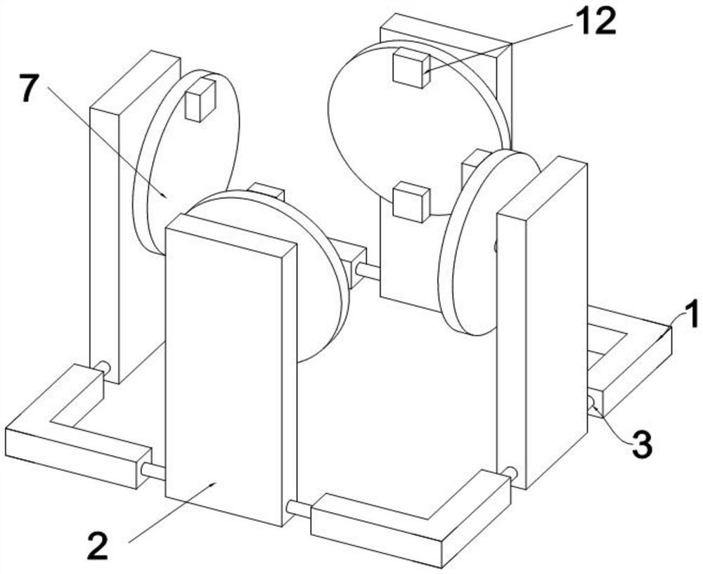
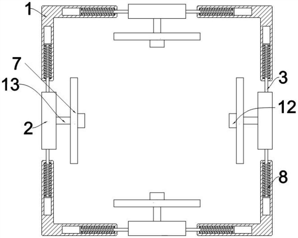
[0025] see Figure 1 to Figure 4, an embodiment provided by the present invention: a magnetic suction electric discharge machining fixture that can match parts with different shapes, including four L-shaped base connecting rods 1, and the L-shaped base connecting rods 1 and adjacent L-shaped bases An electromagnet support plate 2 is arranged between the end and the end of the connecting rod 1, and there are 4 electromagnet support plates 2, and the 4 electromagnet support plates 2 are distributed in a circular array along the vertical center axis of the device. This distribution method makes The fixture has an acting force on the x-axis and y-axis of the workpiece, a...

no. 2 example

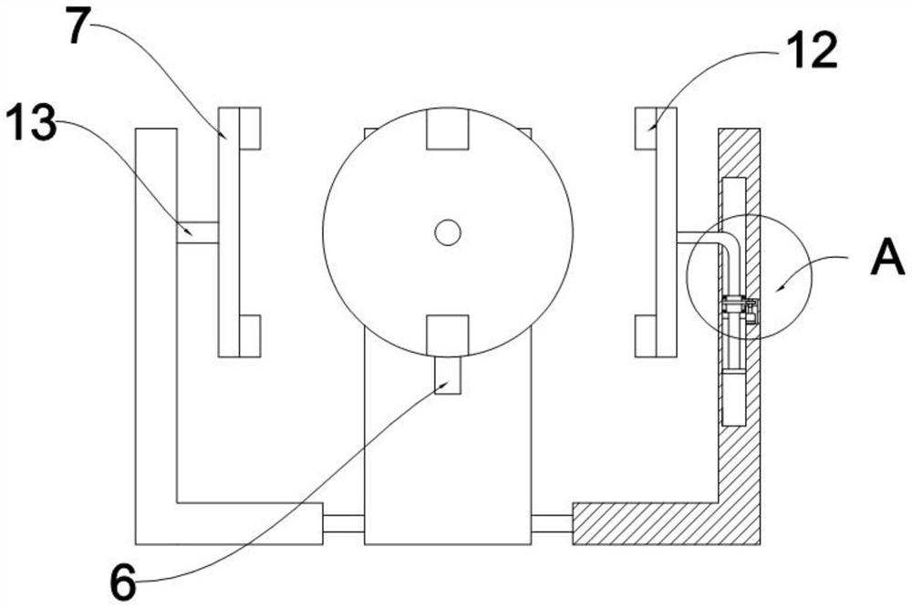
[0031] Based on the magnetic suction type electric discharge machining fixture provided by the first embodiment that can match parts with different shapes, only the clamping operation of the electric discharge machining fixture is realized, but in the actual application process, all surfaces need to be When performing electric discharge machining, it is necessary to perform multiple clamping operations again. Performing clamping operations in the electrolyte solution after EDM not only reduces work efficiency, but also has certain safety hazards. In order to avoid multiple clamping operations With the appearance of the clamping operation, the adjustment operation of the processing surface can be realized during the processing, refer to Figure 1-4 , a magnetic suction type electric discharge machining fixture that can match parts with different shapes also includes an angle sensor fixed inside the elastic splint 7, and the angle sensor is used to detect the relative rotation an...

no. 3 example

[0035] Based on the second embodiment, a magnetic suction EDM fixture that can match parts with different shapes is provided, which only realizes the automatic clamping process for all surface machining during EDM, but in the actual machining process, sometimes It only needs to process any number of surfaces, and there is no fixed angle relationship between several surfaces. At this time, if one surface is clamped one by one, not only the work efficiency will be slow, but also multiple clamping will cause damage to the workpiece. In order to avoid For multiple clamping, the following operations can also be performed in conjunction with the machine tool terminal control system and fixtures:

[0036] After one processing surface of the workpiece is processed, when another specific surface to be processed needs to be processed, similar to the second embodiment, the X surface and the Y surface are preferentially determined, and the Z surface is the moving surface in the vertical di...


PUM


Abstract

The invention discloses a magnetic type clamp for electric spark machining. The clamp can be matched with parts in different shapes and comprises four L-shaped base connecting rods. Electromagnet supporting plates are arranged in the middles of the ends of the L-shaped base connecting rods and the middles of the ends of the adjacent L-shaped base connecting rods. Adjusting connecting rods are fixedly mounted on the two sides of the bottom ends of the electromagnet supporting plates. The other ends of the adjusting connecting rods are movably inserted into the inner sides of the ends of the L-shaped base connecting rods on the sides away from the electromagnet supporting plates. Adjusting springs are arranged on the outer sides of the portions, inserted into the inner sides of the ends of the L-shaped base connecting rods, of the adjusting connecting rods. Waterproof motors are arranged on the upper surfaces of the electromagnet supporting plates. According to the magnetic type clamp, by installation of elastic clamping plates, magnetic fixing blocks and electric telescopic rods, the problems that due to the different shapes of workpieces, clamping and positioning are not facilitated, and actual machining is affected are solved.

Description

technical field [0001] The invention relates to the technical field of electrical discharge machining, in particular to a magnetic suction type clamp for electrical discharge machining. Background technique [0002] With the rapid development of social economy, electric discharge is a kind of processing technology, which mainly uses the discharge electrode (EDM electrode) with a specific geometric shape to burn out the geometric shape of the electrode on the metal (conductive) parts. The electric discharge machining process is often used in For the production of blanking dies and casting molds, EDM is a spark discharge in a liquid medium in a lower voltage range. EDM is mainly completed by a machinery factory. EDM is a self-excited discharge, and its characteristics are as follows: There is a high voltage between the two electrodes of the spark discharge before the discharge. When the two electrodes are close to each other, the medium between them is broken down, and the spa...

Claims


Application Information

Patent Timeline
Patent Type & Authority Applications(China)
IPC IPC(8): B23H11/00B23H1/00
CPCB23H1/00B23H11/003
Inventor 张晓民
Owner 张晓民
Why Eureka
Try Eureka