
Automatic resistance welding device with continuous automatic discharging function

A welding equipment and automatic discharging technology, which is applied in resistance welding equipment, welding equipment, shearing machine equipment, etc., can solve the problems of position deviation of precious metal coating, limiting the application of welding equipment, reducing production line capacity, etc.

Pending Publication Date: 2021-05-25
KUNSHAN YIDING IND TECH CO LTD
View PDF5 Cites 2 Cited by
  • Summary
  • Abstract
  • Description
  • Claims
  • Application Information

AI Technical Summary

Problems solved by technology

[0003] 1. If the joint operation is not completed, the surface treatment production line will automatically shut down, causing all products in the surface treatment production line to be scrapped, causing great losses and reducing the production capacity of the production line;
[0004] 2. In the joint operation, due to improper operation, raw materials will scratch the hands of the operator and cause work-related accidents;
[0006] 4. The smaller and thinner the continuous terminal product material is, the easier it is to deform by manual joint operation, which affects product quality;
[0007] 5. The manual joint of the product is not firm, and it is easy to fall off during the high-speed production process, resulting in shutdown and production stoppage;
[0008] 6. The precision of the manual joint is poor, and the positioning holes of the product cannot be accurately overlapped, resulting in a mismatch between the positioning of the surface treatment product and the precious metal fixture, which causes the position of the precious metal coating to shift, resulting in the product being scrapped;
[0009] 7. The product joints are firmly connected with rivets at the position of the connection belt of the positioning hole, and the connection of the metal terminal part is not very firm, which will cause the terminal to be scattered and scratch the guiding fixture in the process tank, etc., which will deform the product and cause shutdown and production stoppage
However, the welding process is still manual operation, so there are still some problems in the joint operation of continuous terminal product materials, which greatly limits the application of this welding equipment in the automatic continuous surface treatment production line

Method used


Image

  • Automatic resistance welding device with continuous automatic discharging function
  • Automatic resistance welding device with continuous automatic discharging function
  • Automatic resistance welding device with continuous automatic discharging function

Examples


Embodiment Construction

[0051]In order to make the objects, technical solutions, and advantages of the present invention more clearly, the technical solutions in the embodiments of the present invention will be described in contemplation in the embodiments of the present invention, and will be described, and the embodiments described in the embodiments of the present invention will be described. It is a part of the embodiments of the present invention, not all of the embodiments. Based on the embodiments of the present invention, there are all other embodiments obtained without making creative labor without making creative labor premises.

[0052]In the description of the present invention, it is to be understood that the term "one side", "other side", "both sides", "between", "middle", "upper", "lower end" indication or The location relationship is based on the orientation or positional relationship shown in the drawings, is merely intended to be described, and not indicating or implying that the device or c...


PUM


Abstract

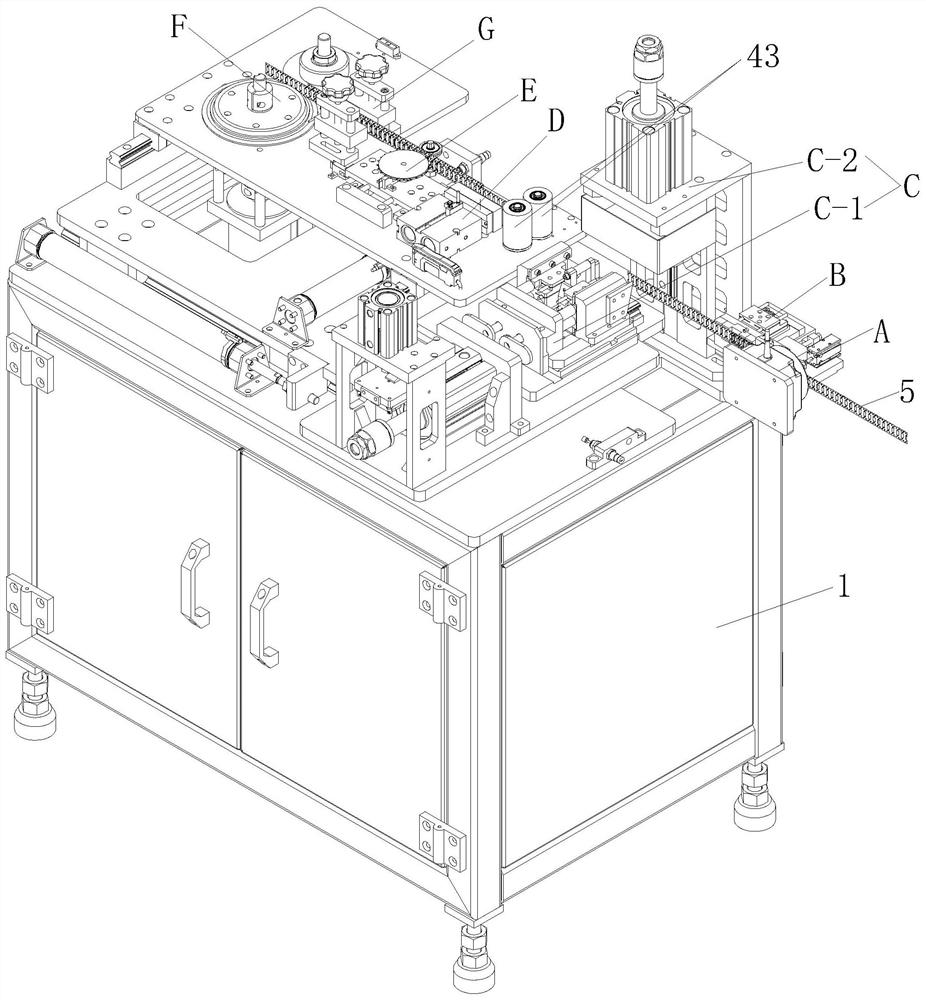
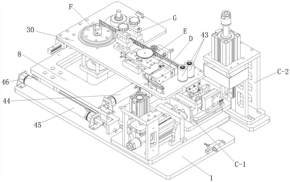
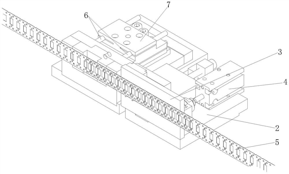
The invention discloses an automatic resistance welding device with a continuous automatic discharging function. The automatic resistance welding device comprises a workbench, a feeding mechanism, a welding mechanism, a cutting mechanism, a pressing mechanism, a positioning mechanism and a traction mechanism, wherein the feeding mechanism is arranged on one side of the workbench; and the welding mechanism, the cutting mechanism, the pressing mechanism, the positioning mechanism and the traction mechanism are sequentially and fixedly arranged on the workbench from the feeding mechanism to the other side. According to the automatic resistance welding device with the continuous automatic discharging function, manual operation is replaced with automatic unwinding and automatic resistance welding, errors caused by manual operation can be greatly reduced, and the production efficiency is greatly improved; and meanwhile, the missing rate of surface treatment products is decreased, the quality of the surface treatment products of continuous metal terminals can be greatly improved, and thus the surface treatment production cost of continuous metal materials is reduced.

Description

Technical field[0001]The present invention relates to the technical field of welding equipment, in particular, a continuous automatic discharge automatic resistance welding device.Background technique[0002]During the process processing of the continuous roll surface treatment line of the electronic industry, first, the surface treatment material is continuously introduced into the surface treatment line through the discharge machine. Due to the rapid development of the electronic industry, many continuous metal electronics continue to develop toward small and miniaturization, the processing speed of high-speed continuous surface treatment line is getting higher and higher; in actual surface treatment production, before the metal material The end of the volume and the head end of the next volume are jointly processed, and the following problems occur with manual operation:[0003]First, the joint operation does not complete the surface processing production line automatic downtime, so ...

Claims


Application Information

Patent Timeline
IPC IPC(8): B23K11/00B23K11/36B23D15/00B23D15/14B23D33/02
CPCB23D15/00B23D15/14B23D33/02B23K11/00B23K11/36
Inventor 门松明珠魏静王跃周爱和
Owner KUNSHAN YIDING IND TECH CO LTD
Learn More