
Niw(x) sputtering target with improved structure

A technology for sputtering targets and metals, which is applied in the field of sputtering targets and can solve problems such as cracks in target material layers

Inactive Publication Date: 2021-05-25
MATERION ADVANCED MATERIALS GERMANY GMBH
View PDF1 Cites 0 Cited by
  • Summary
  • Abstract
  • Description
  • Claims
  • Application Information

AI Technical Summary

Problems solved by technology

In addition, once a certain thickness (usually 3 to 4mm) is exceeded, the direct spraying process can cause cracks in the target material layer

Method used


Image

  • Niw(x) sputtering target with improved structure
  • Niw(x) sputtering target with improved structure

Examples


Embodiment

[0060] In order to illustrate the present invention, several examples and comparative examples were carried out. Spray powders were prepared by mixing elemental powders in a tube mixer for 3 hours. Generally, powders with a particle size in the range of 30 to 120 μm will give suitable results. Especially for W, too large granularity should be avoided. These powder mixtures were used for plasma spraying on SST tubes having an outside diameter (OD) of 133 mm and a length of 550 mm, the ends of which were capped by cap rings.

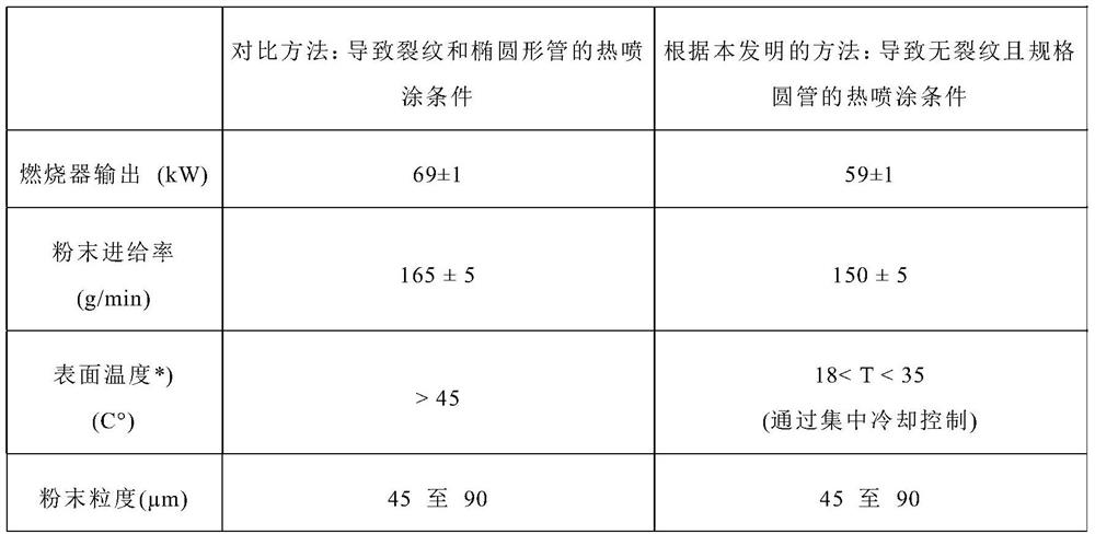
[0061] In Table 1 the thermal spraying conditions for comparative Ni / W / Ta targets and targets according to the invention are listed.

[0062] Table 1:

[0063]


PUM

PropertyMeasurementUnit
Outer diameteraaaaaaaaaa
Lengthaaaaaaaaaa

Abstract

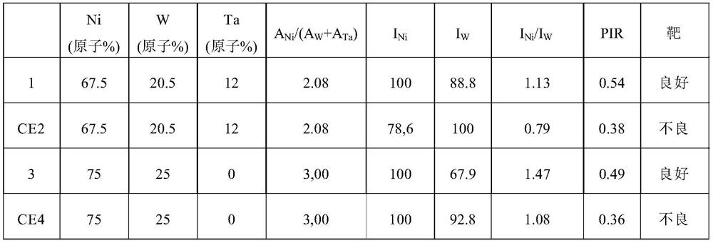
The present invention relates to a sputtering target comprising Ni, W and, optionally, one or more further metal(s) X selected from the group of the refractory metals, Sn, Al and Si, which has a normalized peak intensity ratio PIR=INi / IW*(AW+Ax) / ANi of 0.40 or greater, whereinINi is the intensity of the (111) peak of Ni,IW is the intensity of the (110) peak of W,Aw is the fraction of W in the target in atom%,Ax is the total fraction of the one or more further metals selected from the group of the refractory metals, Sn, Al and Si in the target in atom%,ANi is the fraction of Ni in the target in atom%,and wherein the intensities of the peaks are determined by X-ray powder diffraction using Cu-Kalpha radiation.

Description

technical field [0001] The present invention relates to a sputtering target comprising Ni, W and optionally one or more additional metals X selected from refractory metals, Sn, Al and Si. Background technique [0002] NiW targets are used in electrochromic applications, more recently especially in tubular form. For example, US 2017 / 0003564A1 discloses the use of NiW(X)-oxide based counter electrodes for electrochromic glasses, where X is an optional additional element such as Ta or Nb. [0003] AT14157U1 discloses the production of NiW sputtering targets by using a powder metallurgy route involving hot isostatic pressing (HIP) of powder mixtures at 1100 to 1450°C, and explicitly teaches not to Then use thermal spray. However, HIP and gluing of the sleeve is expensive and, if the target length exceeds 0.5m, results in a segmented target. Since NiW targets are used for oxygen reactive sputtering, the bond gap due to the segmented target structure will lead to redeposition a...

Claims


Application Information

Patent Timeline
IPC IPC(8): C23C14/34C23C4/134C23C4/08C23C4/16C23C14/08
CPCC23C14/3407C23C14/3414C23C4/134C23C4/08C23C4/16C23C14/0021C23C14/085C23C14/083C22C1/0433C22C19/00H01J37/3429H01J37/3491C23C4/06C23C4/067
Inventor M·舒尔特斯M·施洛特
Owner MATERION ADVANCED MATERIALS GERMANY GMBH
Learn More