Spatial positioning method and system

A space positioning and algorithm technology, which is applied in image data processing, instruments, calculations, etc., can solve the problem of decreased positioning accuracy, and achieve high-precision positioning, the required area for layout, small construction costs, and high positioning accuracy.

Pending Publication Date: 2021-05-25
CHINA UNIV OF MINING & TECH
View PDF0 Cites 0 Cited by
  • Summary
  • Abstract
  • Description
  • Claims
  • Application Information

AI Technical Summary

Problems solved by technology

[0003] However, the existing VIO technology can only guarantee the positioning accuracy of the mobile robot in a short period of time. If it runs for a long time, it will inevitably generate positioning accumulation errors, resulting in a significant drop in positioning accuracy during long-term positioning.

Method used


Image

  • Spatial positioning method and system
  • Spatial positioning method and system
  • Spatial positioning method and system

Examples


Embodiment 1

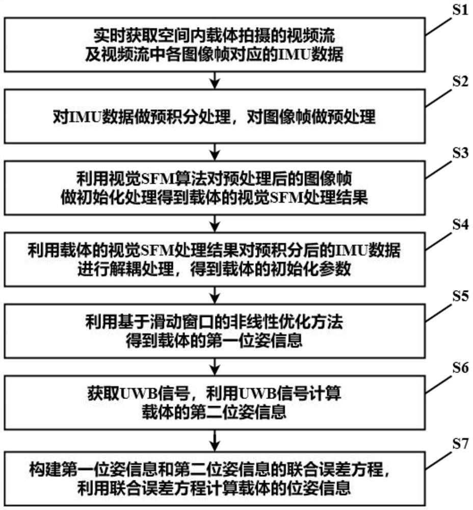
[0083] like figure 1 As shown, it is a flow chart of the spatial positioning method in Embodiment 1 of the present invention, and S1-S7 represent steps of the spatial positioning method.

[0084] Real-time acquisition of the video stream captured by the carrier 6 in the space and the IMU data corresponding to each image frame in the video stream;

[0085] Pre-integrate the IMU data and pre-process the image frame;

[0086] Using the visual SFM algorithm to initialize the preprocessed image frame to obtain the visual SFM processing result of the carrier 6;

[0087] Using the visual SFM processing results of the carrier 6 to decouple the pre-integrated IMU data to obtain the initialization parameters of the carrier 6;

[0088] Obtaining the first pose information of the carrier 6 by using a non-linear optimization method based on a sliding window;

[0089] Obtain the UWB signal, and use the UWB signal to calculate the second pose information of the carrier 6;

[0090] A join...


PUM


Abstract

The invention relates to a spatial positioning method and system, and relates to the technical field of positioning. The spatial positioning system comprises a monocular camera module, an IMU processing module and a UWB processing module. The method comprises the following steps: acquiring a video stream shot by a carrier in a space by using a monocular camera module, and acquiring IMU data of the carrier by using an IMU processing module; performing initialization processing on the preprocessed image frame by using a visual SFM algorithm to obtain a visual SFM processing result of the carrier; performing decoupling processing on the IMU data after pre-integration by utilizing a visual SFM processing result to obtain an initialization parameter of the carrier; performing real-time optimization on the carrier based on a sliding window to obtain first pose information of the carrier; enabling the UWB processing module to obtain a UWB signal and calculate second pose information of the carrier; and finally, calculating the pose information of the carrier based on a joint error equation of the first pose information and the second pose information. According to the method, the problem of positioning accumulated errors caused by long-time positioning only by using the VIO technology is solved, and the long-time positioning precision of the carrier in the space is greatly improved.

Description

technical field [0001] The present invention relates to the technical field of positioning, in particular to a spatial positioning method and system. Background technique [0002] Visual Inertial Odometry (Visual Inertial Odometry, VIO) is used for the navigation and self-positioning of mobile robots, and uses the acquired positioning information of mobile robots to realize the positioning of the space where mobile robots are located. VIO includes a monocular camera and an inertial measurement unit (Inertial Measurement Unit, IMU). Among them, the monocular camera realizes the positioning and navigation of the mobile robot itself according to the captured video stream, and the IMU is combined with the monocular camera to solve the scale ambiguity problem existing in the positioning and navigation of the monocular camera and improve the robustness of the system. [0003] However, the existing VIO technology can only guarantee the positioning accuracy of the mobile robot in a...

Claims


Application Information

Patent Timeline
IPC IPC(8): G06T7/73
CPCG06T7/73G06T2207/10016G06T2207/20016
Inventor 李增科刘振彬邵克凡张秋昭
Owner CHINA UNIV OF MINING & TECH
Why Eureka
Try Eureka