Vacuum drying device

A vacuum drying device and drying treatment technology, which is applied in the direction of semiconductor devices, electrical components, circuits, etc., can solve the problems of different gas flow rates and directions, improve luminous efficiency and service life, improve yield, and display defects and flatness keep consistent effect

Pending Publication Date: 2021-05-25
SHENZHEN CHINA STAR OPTOELECTRONICS SEMICON DISPLAY TECH CO LTD
View PDF7 Cites 1 Cited by
  • Summary
  • Abstract
  • Description
  • Claims
  • Application Information

AI Technical Summary

Problems solved by technology

[0005] The embodiment of the present application provides a vacuum drying device, which is used to solve the problem that the flow velocity and direction of the gas in each part above the heating plate are different in the existing vacuum drying device

Method used


Image

  • Vacuum drying device
  • Vacuum drying device

Examples


Embodiment Construction

[0025] The following descriptions of the various embodiments refer to the accompanying drawings to illustrate specific embodiments that the present application can be used to implement. The directional terms mentioned in this application, such as [top], [bottom], [front], [back], [left], [right], [inside], [outside], [side], etc., are for reference only The orientation of the attached schema. Therefore, the directional terms used are used to illustrate and understand the application, but not to limit the application. In the figures, structurally similar elements are denoted by the same reference numerals.

[0026] The present application will be further described below in conjunction with the accompanying drawings and specific embodiments.

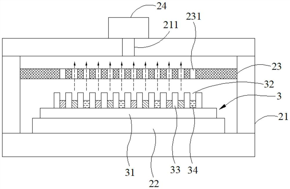
[0027] The embodiment of the present application provides a vacuum drying device, the vacuum drying device is used to dry the display substrate, combined with figure 2 Describe in detail. Such as figure 2 as shown, figure 2 Schema...


PUM

PropertyMeasurementUnit
thicknessaaaaaaaaaa
thicknessaaaaaaaaaa

Abstract

The invention provides a vacuum drying device which comprises a box body, a heating mechanism, a mask plate and an air exhaust mechanism, the mask plate is arranged on the side, away from the bottom of the box body, of the heating mechanism, and a display substrate comprises a plurality of sub-pixel units which are arranged in an array mode and used for being filled with ink materials. The mask plate is provided with a plurality of sub-pixel openings corresponding to the sub-pixel units on the display substrate in a one-to-one mode, a suction force of the air exhaust mechanism is evenly dispersed to the sub-pixel units on the display substrate through the sub-pixel openings in the mask plate, and it is guaranteed that the volatilization direction and the volatilization speed of solvents in ink materials in the sub-pixel units are the same, therefore, the surface flatness of a film layer formed after the ink material in each sub-pixel unit is dried is kept consistent.

Description

technical field [0001] The present application relates to the field of display technology, in particular to a vacuum drying device. Background technique [0002] The organic light emitting diode (OLED) display panel has the advantages of self-illumination, high contrast ratio, thin thickness, wide viewing angle, and fast response speed, and is considered to be the next-generation mainstream display technology. Inkjet printing technology is a technology for producing organic light-emitting diodes by spraying less than tens of picoliters of organic light-emitting materials. It can also be produced under the environment, and can effectively improve the use efficiency of organic materials, so it is considered to be the most potential preparation technology for large-scale OLED display panels. [0003] The existing inkjet printing technology needs to dissolve the organic luminescent material in a solvent to make it into ink, spray it between the pixel definition layers of the dr...

Claims


Application Information

Patent Timeline
Patent Type & Authority Applications(China)
IPC IPC(8): H01L51/56
CPCH10K71/135H10K71/40
Inventor 赵紫怡郝鹏
Owner SHENZHEN CHINA STAR OPTOELECTRONICS SEMICON DISPLAY TECH CO LTD
Why Eureka
Try Eureka