Water-cooling circulating device for hazardous waste incineration flue gas

A water-cooling cycle and flue gas incineration technology, applied in the field of flue gas water-cooling cycle, can solve the problems of inability to ensure continuous operation of equipment, short service life of heat exchangers, blockage of salt deposits, etc., and achieve long-term stable operation, increased service life, Corrosion reduction effect

Active Publication Date: 2021-05-28
上海域德环保股份有限公司
View PDF4 Cites 0 Cited by
  • Summary
  • Abstract
  • Description
  • Claims
  • Application Information

AI Technical Summary

Problems solved by technology

There is a large amount of salt in the circulating lye, which will cause serious salt corrosion during heat exchange. At the same time, salt blockage will occur. After a period of operation, the furnace needs to be shut down for cleaning, which cannot guarantee the continuous operation of the equipment. In addition, the use of heat exchangers Very short lifespan, requiring replacement in a few months

Method used


Image

  • Water-cooling circulating device for hazardous waste incineration flue gas
  • Water-cooling circulating device for hazardous waste incineration flue gas
  • Water-cooling circulating device for hazardous waste incineration flue gas

Examples


Embodiment Construction

[0031] The following will clearly and completely describe the technical solutions in the embodiments of the present invention with reference to the accompanying drawings in the embodiments of the present invention. Obviously, the described embodiments are only some, not all, embodiments of the present invention. Based on the embodiments of the present invention, all other embodiments obtained by persons of ordinary skill in the art without making creative efforts belong to the protection scope of the present invention.

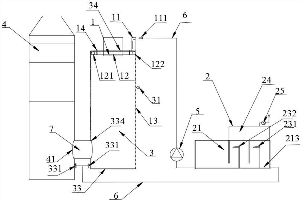
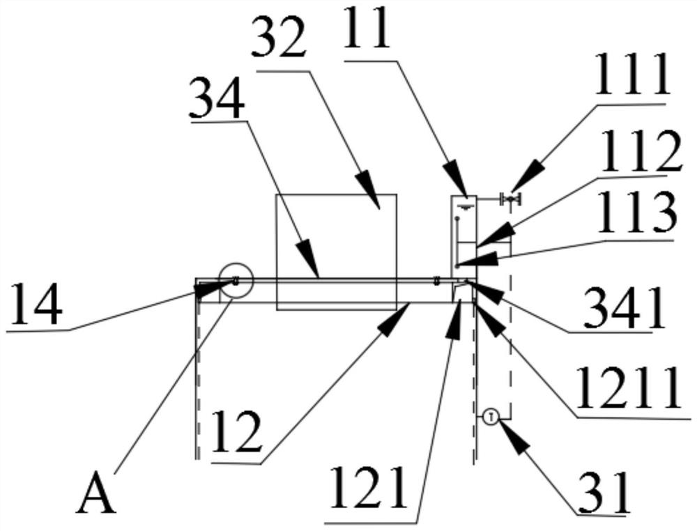
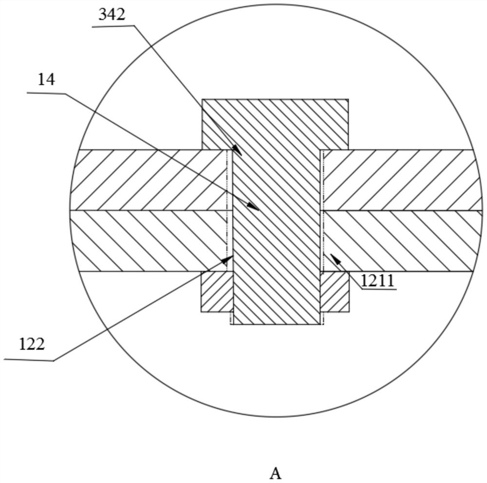
[0032] Such as Figure 1~3 As shown, a hazardous waste incineration flue gas water cooling circulation device includes a cooling device 1, a circulation device 2, a first deacidification tower 3, a second deacidification tower 4, a water pipe 6 and a flue gas pipeline 7, and the first deacidification tower The sides of 3 are tightly connected with the side of the second deacidification tower 4 through the flue gas pipeline 7, the first deacidification tower 3 ...


PUM


Abstract

The invention discloses a water cooling circulation device which comprises a cooling device, a circulation device, a first deacidification tower and a second deacidification tower, the side face of the first deacidification tower is fixedly connected with the side face of the second deacidification tower through a flue gas pipeline, the first deacidification tower and the second deacidification tower are connected with the circulation device through water pipes, and the circulation device is connected with the cooling device through a water pipe. The cooling device is fixedly connected with the first deacidification tower and comprises a water tank and a distribution ring, the distribution ring is provided with a distribution ring groove, a plurality of ring groove water outlets are formed in the bottom end of the distribution ring groove, the first deacidification tower comprises a tower body, a water inlet hole is formed in the top end of the tower body, the ring groove water outlets face the inner wall face of the first deacidification tower, and the bottom of a circulating pool extends upwards to be fixedly connected with two supporting plates. The upper end of the circulating pool extends downwards to be fixedly connected with two partition plates, the supporting plates and the partition plates are arranged at intervals, and the upper ends of the supporting plates are fixedly connected with the side faces of a first-stage evaporation platform and a second-stage evaporation platform respectively.

Description

technical field [0001] The invention relates to the technical field of flue gas water cooling cycle, in particular to a hazardous waste incineration flue gas water cooling cycle device. Background technique [0002] The hazardous waste incineration system is equipped with a deacidification tower after the dust collector. The material of the deacidification tower is generally FRP. The normal temperature of domestic FRP does not exceed 150°C. The flue gas at the outlet of the dust collector is usually between 160-180°C. When entering the FRP deacidification tower, it will exceed the tolerance temperature of FRP, which will cause the deacidification tower to soften and deform, and even cause a safety accident that the deacidification tower collapses. For this reason, it is necessary to cool down the flue gas before it enters the FRP deacidification tower. Usually, water spraying is used to cool down. Since the water spraying cooling in this area coincides with the low-temperatu...

Claims


Application Information

Patent Timeline
Patent Type & Authority Applications(China)
IPC IPC(8): B01D53/40B01D53/75B01D53/78B01D53/96F23J15/00F23J15/04F23J15/06
CPCB01D53/40B01D53/75B01D53/78B01D53/96B01D2258/0283F23J15/003F23J15/006F23J15/04F23J15/06F23J2219/40
Inventor 朱海滨陶经坚乔德友程强祥
Owner 上海域德环保股份有限公司
Why Eureka
Try Eureka