Glue filling device of filter for rail transit

A rail transit and filter technology, applied in the field of automation equipment, can solve the problems of restricting production efficiency, affecting performance, difficult to set up a preheating device, etc., eliminating the need for a preheating device and a cleaning device, reducing adverse effects, and small sealing space. Effect

Active Publication Date: 2021-05-28
安徽博格韦尔电气股份有限公司
View PDF6 Cites 3 Cited by
  • Summary
  • Abstract
  • Description
  • Claims
  • Application Information

AI Technical Summary

Problems solved by technology

[0003] The glue filling equipment used by our company before is still the mainstream traditional vacuum glue filling equipment in the market, but in the actual production process, some air bubbles often appear, especially at the corners of the inner wall of the filter component, which affects its performance. The product The good product rate is low. In order to reduce the generation of air bubbles, the traditional methods currently used are as follows:
[0004] (1) During the stirring process, the main agent and the curing agent are mixed together for vacuum treatment. This method has been used in vacuum glue filling equipment, and the effect is not ideal;
[0005] (2) Heat the sealing object in advance to automatically eliminate the air bubbles. The existing vacuum glue filling equipment does not have the above functions, and additional settings are required, and the existing glue filling process adopts an assembly line, so it is difficult to set a fixed preset time. heating device;
[0006] (3) Put the mixed material into an oven for drying. The post-processing period of this method is long, which restricts the production efficiency

Method used


Image

  • Glue filling device of filter for rail transit
  • Glue filling device of filter for rail transit
  • Glue filling device of filter for rail transit

Examples


Embodiment Construction

[0039] In order to make the technical means, creative features, goals and effects achieved by the present invention easy to understand, the present invention will be further described below in conjunction with specific embodiments.

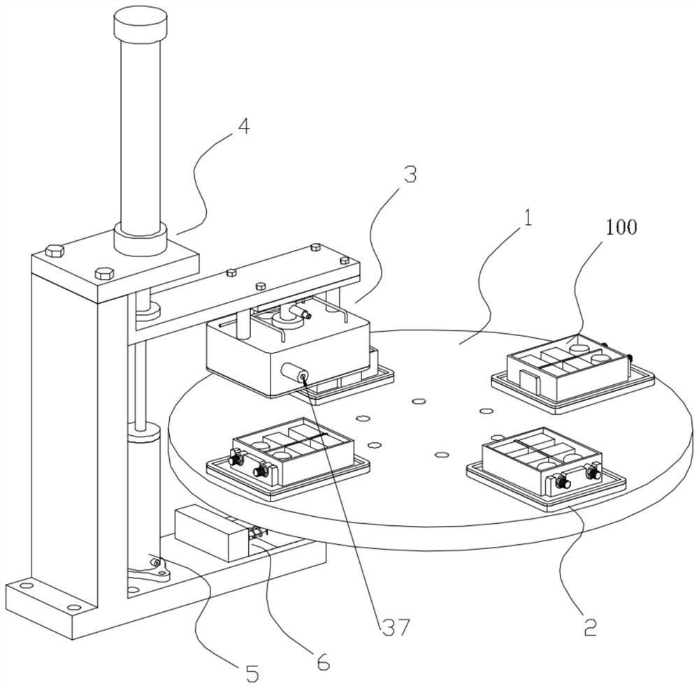
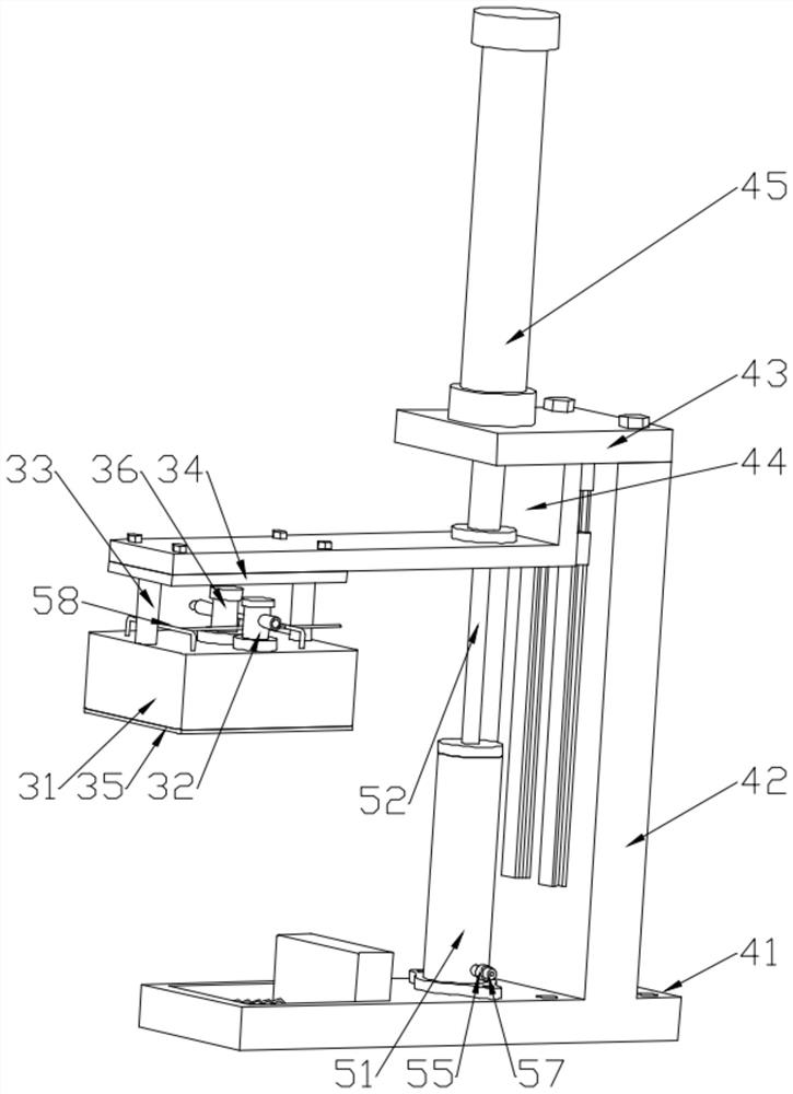
[0040] Such as Figure 1 to Figure 10 As shown, a glue filling device for a rail transit filter includes a rotating disc 1, a positioning tool 2, a vacuum assembly 3, a driving mechanism 4, a glue filling head 36, and a heating assembly 5;

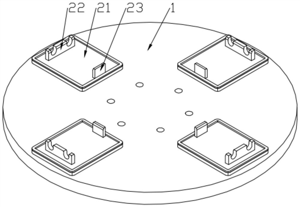
[0041] The rotating disc 1 is rotatably connected to the workbench and can rotate in a certain direction at a fixed angle and beat;

[0042] The positioning tooling 2 is arranged on the rotating disc 1 in a plurality of circumferential directions, and the positioning tooling 2 is used to place the filter assembly 100 to be processed;

[0043]The vacuum assembly 3 is located directly above one of the positioning tools 2 and is connected to the drive mechanism 4. When the vacuum assembly 3 descends to the lowes...


PUM


Abstract

The invention discloses a glue filling device of a filter for rail transit, and relates to the field of automation equipment. The glue filling device comprises a rotary disc, a positioning tool, a vacuumizing assembly, a driving mechanism, a glue filling head and a heating assembly. The rotary production layout is adopted, and compared with traditional linear assembly line type vacuum glue filling equipment, each product sealing space is smaller in sealing space, and therefore the vacuumizing efficiency is higher; in addition, by means of downward movement of the driving mechanism, the heating assembly can be driven to operate and generate high-temperature and high-pressure compressed gas, and then the compressed gas is sprayed to the inner wall of a filter assembly by means of gas spraying pipes to preheat the inner wall of the filter assembly, so that the probability of bubble generation is reduced; and meanwhile, due to the fact that the gas spraying pipes are located right above the four corners of the inner wall of the filter assembly, high-speed gas flow generated by the high-pressure gas can blow up impurities which are difficult to remove at the corners, and then the impurities are pumped away and discharged by means of an exhaust pipe, so that the adverse effect of the impurities on the filling quality is reduced.

Description

technical field [0001] The invention belongs to the field of automation equipment, and in particular relates to a glue filling device for a rail transit filter. Background technique [0002] Filters are widely used in the field of rail transit because of their functions of filtering out interference noise or performing spectrum analysis. During the filter assembly process, the filter components need to be potted with glue. Generally, flame-retardant silicone potting glue is used. It has a high thermal conductivity and is potted to the edge of the shell. After curing, the integrated reactor and capacitor are all covered, and the heat can be fully transferred to the shell through the potting glue, achieving good heat dissipation and shock resistance. Waterproof effect. [0003] The glue filling equipment used by our company before is still some of the mainstream traditional vacuum glue filling equipment in the market, but in the actual production process, some air bubbles oft...

Claims


Application Information

Patent Timeline
Patent Type & Authority Applications(China)
IPC IPC(8): B05C13/02B05C9/14B05D3/04B08B5/02B08B15/04
CPCB05C9/14B05C13/02B05D3/0413B08B5/02B08B15/04
Inventor 张春玲童来奇周华山
Owner 安徽博格韦尔电气股份有限公司
Why Eureka
Try Eureka