
Forming tool for locking flanging-riveting nut

A technology for forming tooling and nuts, applied in the directions of forming tools, nuts, manufacturing tools, etc., can solve the problems of low production efficiency and high production cost of stop turning rivet nuts, and achieve the effects of improving convenience, efficiency and high forming accuracy

Active Publication Date: 2021-05-28
河南航天精工制造有限公司
View PDF14 Cites 0 Cited by
  • Summary
  • Abstract
  • Description
  • Claims
  • Application Information

AI Technical Summary

Problems solved by technology

[0005] The purpose of the present invention is to provide a stop turning rivet nut forming tool to solve the problems of low production efficiency and high production cost of stop turning rivet nuts in the prior art technical problem

Method used


Image

  • Forming tool for locking flanging-riveting nut
  • Forming tool for locking flanging-riveting nut
  • Forming tool for locking flanging-riveting nut

Examples


Embodiment 1

[0042] The structure of the stop turning rivet nut forming tooling is as follows: Figure 4 As shown, including base 9 and punch 10.

[0043] Base 9 is used to be installed on the workbench of press, and its structure is as Figure 5 As shown, the base 9 includes a positioning cylinder 11 and a stopper 12 located on the outer peripheral surface of the positioning cylinder 11. The diameter of the inner cavity 13 of the positioning cylinder 11 is not smaller than the outer diameter of the threaded section 1 of the nut blank, which can make the threaded section of the nut blank 1 is inserted to avoid the threaded section 1, and the upper end surface of the positioning cylinder 11 is used as a stop fitting surface, which can stop and cooperate with the end surface of the annular boss 3 of the nut blank facing the threaded section 1 side, such a positioning cylinder 11 acts as a nut The installation structure enables the nut blank to be installed on the base 9 .

[0044] A plural...

Embodiment 2

[0052] Embodiment 2 of the stop turning rivet nut forming tool in the present invention, the difference between this embodiment and embodiment 1 is that the stop turning rivet nut forming tool in embodiment 1 includes a punch and a base. In this embodiment, Stop rivet nut forming tooling has punches only.

Embodiment 3

[0053] Embodiment 3 of the stop turning riveting nut forming tool in the present invention, the difference between this embodiment and Embodiment 1 is that the lower end surface of the pressing block in Embodiment 1 is a plane perpendicular to the axis of the nut blank. Among them, the lower end surface of the pressing block is a slope that gradually slopes upward from the inside to the outside along the radial direction of the nut blank, so as to ensure that the part of the annular protrusion that is stamped and deformed by the stamping surface is deformed outward.


PUM


Abstract

The invention relates to a forming tool for a locking flanging-riveting nut. The forming tool comprises a punch used for being arranged on a pressing head of a press machine and provided with a punching end, wherein the punching end is provided with two or more pressing blocks annularly distributed at intervals, and the lower end face of each pressing block is a punching face used for punching an annular protrusion of a nut blank; in the radial direction of the nut blank, the radial size of each punching face is not smaller than the height of the annular protrusion; a flanging-riveting section receding structure for receding the flanging-riveting section of the nut blank is arranged in the area defined by the pressing blocks annularly arranged at intervals; and a plurality of notches are directly punched in the annular protrusion of the nut blank in a punching mode, so that locking teeth can be rapidly and efficiently formed on the side face, facing the flanging-riveting section, of the annular protrusion of the nut blank, the manufacturing efficiency of the locking flanging-riveting nut is improved, and then the production cost of the locking flanging-riveting nut is reduced.

Description

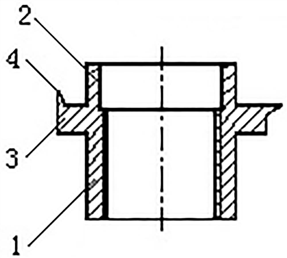
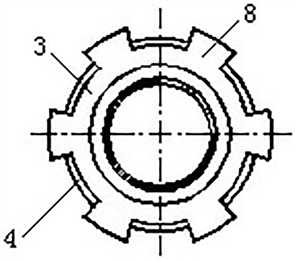
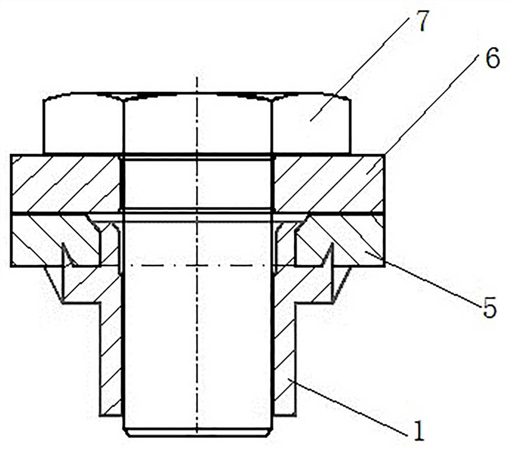
technical field [0001] The invention relates to a forming tool for a stop turning riveting nut. Background technique [0002] In industrial production, the connection of thin-walled parts is often involved. For example, in the assembly of aircraft or engines, it is necessary to connect some thin-walled parts of aluminum substrates. In the prior art, rivets are often used for riveting in such cases. The disadvantages of this riveted connection method are: after assembly, if some parts need to be debugged or some parts are assembled in an improper position, the rivets need to be removed, but the riveted rivets are extremely difficult to remove, and the matrix is ​​easy to be damaged during the removal process. And it takes a long time to dismantle, time-consuming and labor-intensive. [0003] In view of such problems, in the prior art, rivet nuts and bolts are used to replace the riveting of rivets, such as figure 1 with figure 2 A stop turning riveting nut shown includes ...

Claims


Application Information

Patent Timeline
Patent Type & Authority Applications(China)
IPC IPC(8): B21D37/10B21D53/24
CPCB21D37/10B21D53/24
Inventor 刘前峰付建建石大鹏韦波安蒙谢茂阳杨冬梅曹宇萱何坤
Owner 河南航天精工制造有限公司
Learn More