
Sliding type crushing mechanism with rocker arm power

A crushing mechanism, sliding technology, applied in cutting machinery, driving device, slitting machinery, etc., can solve the problem of insufficient space for cutting motor and cable slot, low power density of rocker arm height, and inability of conveyor to transport, etc. to solve the problem of power source, save installation space and compact structure

Pending Publication Date: 2021-05-28
SHANGHAI TIANDI MINING EQUIP TECH CO LTD +2
View PDF0 Cites 0 Cited by
  • Summary
  • Abstract
  • Description
  • Claims
  • Application Information

AI Technical Summary

Problems solved by technology

[0002] In order to adapt to the mining of thin or high-grade thin ore seams, the rocker arm of the high-power (high torque) cutting system is usually used on the bauxite mining machine. The height of the rocker arm is low, the structure is compact, and the power density is high. The cutting motor occupies a large space in the front and rear direction, so that there is not enough space between the cutting motor and the cable trough to set up a conventional crushing device
However, in the actual mining of mining machines, there are often a large number of high-hardness bauxite rocks. After entering the conveyor, these bauxite rocks need to pass under the position where the cutting motor of the rocker arm is located, but many of them are large rocks. Unable to pass through, the final accumulation will cause the conveyor to fail to convey, and it needs to be shut down for manual cleaning, which is time-consuming and laborious, and also affects production capacity

Method used


Image

  • Sliding type crushing mechanism with rocker arm power
  • Sliding type crushing mechanism with rocker arm power
  • Sliding type crushing mechanism with rocker arm power

Examples


Embodiment Construction

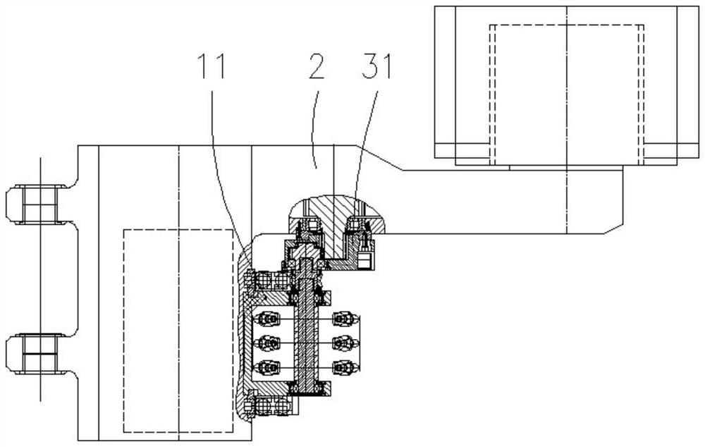
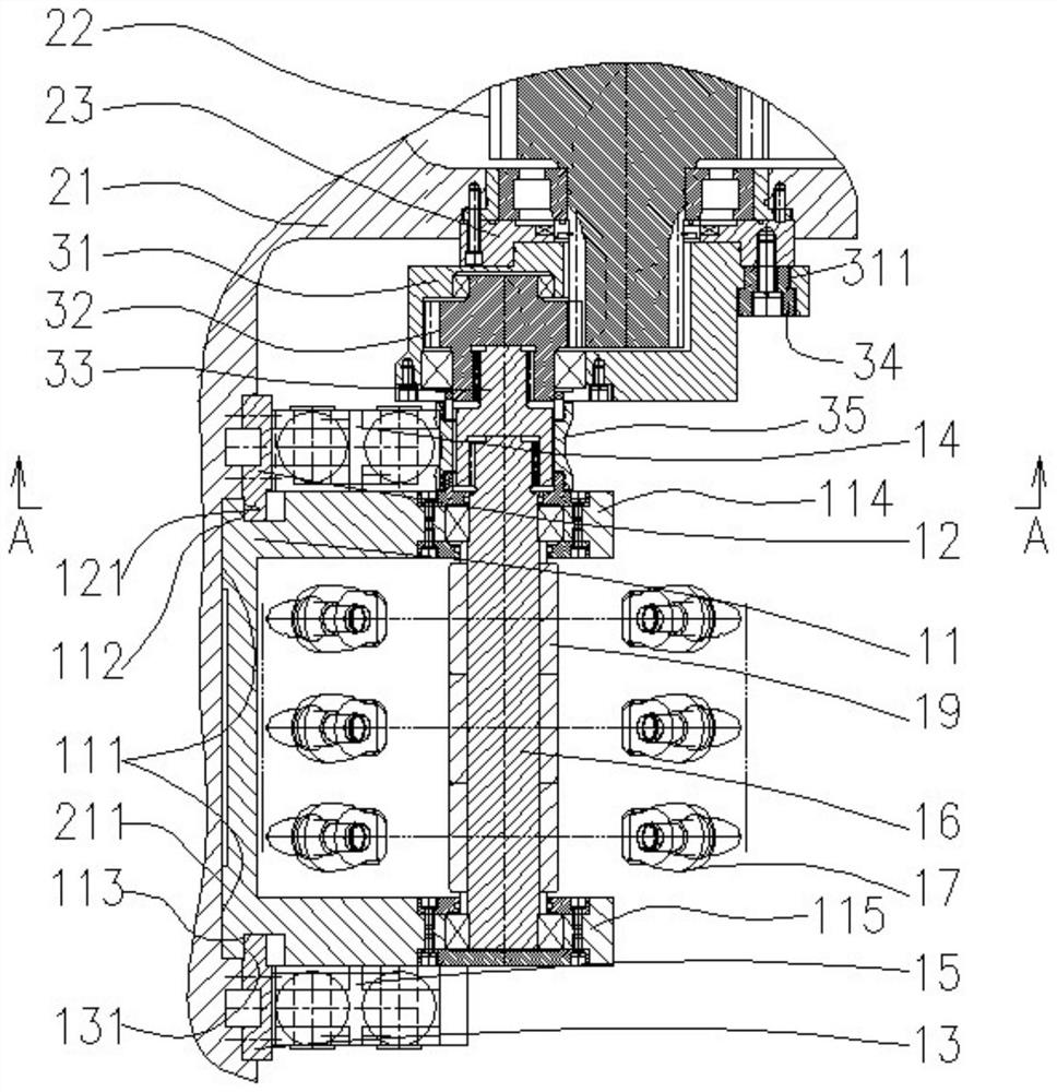
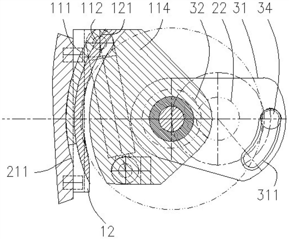
[0033] The invention discloses a sliding crushing mechanism (referred to as crushing mechanism) with rocker arm power, such as Figure 1-6 As shown, it includes a sliding seat 11, a swing housing 31, a crushing tooth assembly and a rocker arm 2 of a mining machine. A front support arm 114 and a rear support arm 115 are provided on the sliding seat. The crushing tooth assembly includes a rotating shaft 16, a plurality of sleeves 19 sleeved side by side on the rotating shaft, and crushing teeth 17 mounted on the sleeves. The front part and the rear part of the rotating shaft are rotatably supported on the front supporting arm and the rear supporting arm respectively, and the rotating shaft extends horizontally forward and backward. The swing housing is located at the rear side of the boom portion 21 of the rocker arm of the mining machine and in front of the front support arm. The rear end of a transmission gear 22 in the rocking arm of the mining machine passes through the re...


PUM


Abstract

The invention relates to a sliding type crushing mechanism with rocker arm power. The sliding type crushing mechanism comprises a sliding seat, a swinging shell and a crushing tooth assembly, wherein the crushing tooth assembly comprises a rotating shaft and crushing teeth mounted on the rotating shaft; the front part and the rear part of the rotating shaft are respectively and rotatably supported on a front supporting arm and a rear supporting arm of the sliding seat; the swinging shell is fixed in front of the front supporting arm; the rear end of a transmission gear in a rocker arm penetrates through the rocker arm to enter an inner cavity of the swinging shell and is in transmission connection with the front end of the rotating shaft through a transmission system in the swinging shell; the swinging shell is hinged to the rocker arm; the hinged part is coaxial with the transmission gear; the transmission gear is not coaxial with the rotating shaft; the sliding seat is in sliding connection relative to the rocker arm according to a circular arc-shaped track taking the axis of the transmission gear as an axis; and under the driving of an oil cylinder, the sliding seat drives the swinging shell to swing around the transmission gear. The sliding type crushing mechanism can be used for a mining machine for mining a thin ore bed or a high-grade thin ore bed and can be used for effectively crushing rock blocks, so that the rock blocks can smoothly pass through the lower side of the rocker arm of the mining machine and are prevented from being stacked.

Description

technical field [0001] The invention relates to a crushing mechanism for a mining machine, especially suitable for a mining machine for mining relatively thin ore layers or high-grade thin ore layers. Background technique [0002] In order to adapt to the mining of thin or high-grade thin ore seams, the rocker arm of the high-power (high torque) cutting system is usually used on the bauxite mining machine. The height of the rocker arm is low, the structure is compact, and the power density is high. The advanced cutting motor occupies a large space in the front and rear direction, so that there is not enough space between the cutting motor and the cable trough to set up a conventional crushing device. However, in the actual mining of mining machines, there are often a large number of high-hardness bauxite rocks. After entering the conveyor, these bauxite rocks need to pass under the position where the cutting motor of the rocker arm is located, but many of them are large rock...

Claims


Application Information

Patent Timeline
Patent Type & Authority Applications(China)
IPC IPC(8): E21C31/02E21C31/08E21C35/19E21C25/06
CPCE21C25/06E21C31/02E21C31/08E21C35/19
Inventor 胡滔章立强王振乾郭岱胡璟宋振陈峤鹰董超顾恩洋丁海春宋学平李继林曹光熙杨芸朱孝仁王兆胜卢祺良翁洋洋方兴朱承才顾英龙
Owner SHANGHAI TIANDI MINING EQUIP TECH CO LTD
Learn More