Liquid-driven ultrahigh-pressure compressed air energy storage system and method

A compressed air energy storage and ultra-high pressure technology, applied in the field of energy storage, can solve the problems of large volume, high cost and low energy storage density of artificially built pressure vessels

Active Publication Date: 2021-05-28
BEIHANG UNIV +1
View PDF10 Cites 0 Cited by
  • Summary
  • Abstract
  • Description
  • Claims
  • Application Information

AI Technical Summary

Problems solved by technology

However, it has not yet been applied on a large scale. The bottleneck lies in: low energy storage density, relying on natural caves to store compressed air, and artificially built pressure vessels with large volume and high cost

Method used


Image

  • Liquid-driven ultrahigh-pressure compressed air energy storage system and method
  • Liquid-driven ultrahigh-pressure compressed air energy storage system and method
  • Liquid-driven ultrahigh-pressure compressed air energy storage system and method

Examples


Embodiment

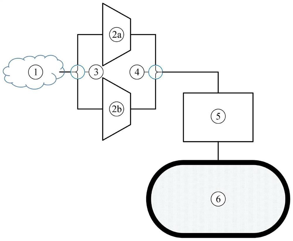
[0025] The embodiment of the invention discloses a liquid-driven ultra-high pressure compressed air energy storage system, which consists of a low-pressure air compressor (2a), a low-pressure expander (2b), a liquid piston high-pressure subsystem (5) and a high-pressure gas storage tank (6) composition. Including the following processes: low-pressure compression process, gas-liquid pressurization process, gas-liquid expansion process and low-pressure expansion process;

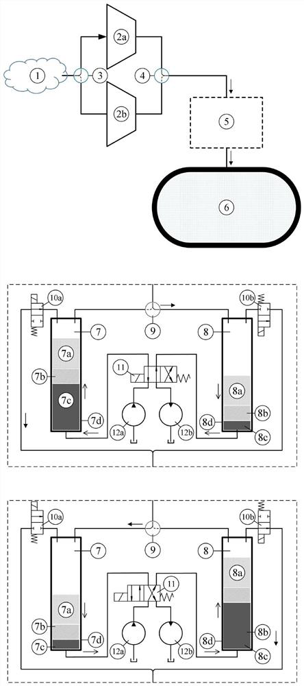
[0026] When storing energy, the air enters the high-pressure air storage tank (6) after the energy is stored through the low-pressure compression process and the gas-liquid pressurization process;

[0027] The low-pressure compression process: the atmosphere (1) is sucked into the low-pressure compressor (2a), and the air is compressed to obtain low-pressure air to be discharged;

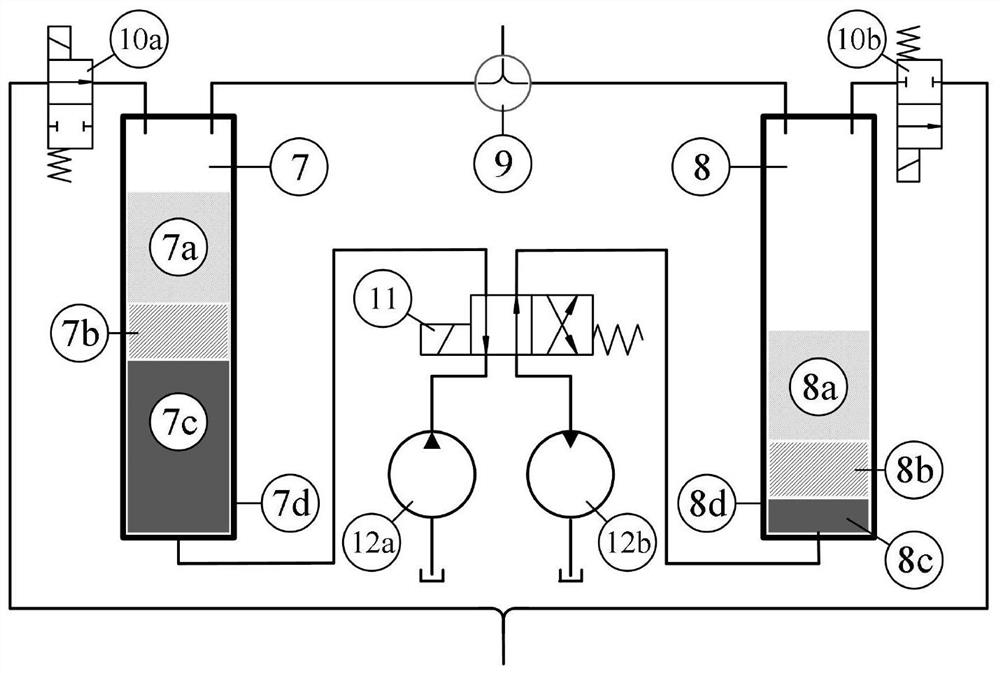
[0028] The gas-liquid pressurization process: low-pressure air is charged into the cylinder body (8d) through the pilot valve (9)...


PUM


Abstract

The invention discloses a liquid-driven ultrahigh-pressure compressed air energy storage system and method. Electric energy is stored in ultrahigh-pressure air in the form of energy, and the compressed air storage pressure is higher than 25 MPa. The air works in a low-pressure state and a high-pressure state, when the air works in the low pressure state, an industrial compressor and an expansion machine which are of non-reciprocating structures such as a screw type, a centrifugal type and an axial-flow type are adopted, and when the air works in the high pressure state, a hydraulic pump and a hydraulic motor are adopted to pressurize and depressurize the air; and by the adoption of a liquid piston structure composed of a heat transfer layer, an isolation layer and a transmission layer, the problems of ultrahigh-pressure air sealing and heat dissipation are solved, ultrahigh-pressure compressed air energy storage is achieved, the energy storage density is improved, and the storage cost is reduced.

Description

technical field [0001] The invention relates to the technical field of energy storage, and more specifically relates to a liquid-driven ultra-high pressure compressed air energy storage system and a method thereof. Background technique [0002] With the development of renewable energy technology, its popularity will reach an unprecedented high level, and how to better match it with the electricity market has become a top priority. The proportion of renewable energy power generation in grid transmission power continues to increase, and the cost of grid connection has an increasing impact on its total cost. [0003] At present, my country mainly uses coal, oil and natural gas to generate electricity, and thermal power can adjust the balance between supply and demand. In the future, the proportion of thermal power installed capacity will decline year by year and will remain so for a long time. The proportion of thermal power generation in my country will continue to decline, w...

Claims


Application Information

Patent Timeline
Patent Type & Authority Applications(China)
IPC IPC(8): F04B37/12F04B41/02F04B41/06F04B39/00
CPCF04B37/12F04B39/0011F04B41/02F04B41/06Y02E60/16
Inventor 许未晴胡昱石岩杜丙同李晶
Owner BEIHANG UNIV
Why Eureka
Try Eureka