A soil-structure contact surface shear test device capable of bidirectional high-frequency vibration

A technology of shear test and high-frequency vibration, applied in the direction of applying stable shear force to test the strength of materials, measuring devices, instruments, etc., can solve problems such as normal force fluctuations on the contact surface, and achieve constant vertical pressure output, Avoid the effect of normal pressure fluctuations

Active Publication Date: 2022-05-20
TONGJI UNIV
View PDF12 Cites 0 Cited by
  • Summary
  • Abstract
  • Description
  • Claims
  • Application Information

AI Technical Summary

Problems solved by technology

[0012] The purpose of the present invention is to provide a soil-structure contact surface shear test device that can realize two-way high-frequency vibration. The problem that the normal inertial force causes the normal force of the contact surface to fluctuate

Method used


Image

  • A soil-structure contact surface shear test device capable of bidirectional high-frequency vibration
  • A soil-structure contact surface shear test device capable of bidirectional high-frequency vibration
  • A soil-structure contact surface shear test device capable of bidirectional high-frequency vibration

Examples


Embodiment 1

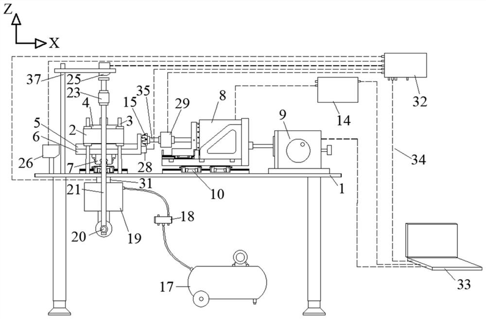
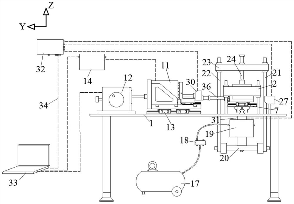
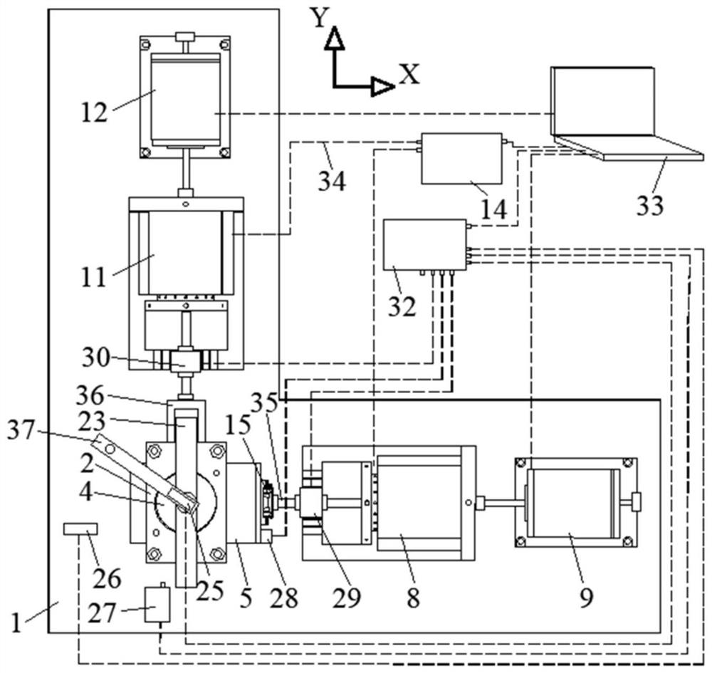
[0039] Such as figure 1 , figure 2 , image 3 , Figure 4 , Figure 5 As shown, a soil-structure interface shear test device that can realize bidirectional high-frequency vibration includes a test unit, a loading unit (for horizontal loading and Z-direction loading) and a measurement and control unit (for measurement acquisition and control) . Relevant components mainly include: test bench 1, upper shear box 2, upper shear box fixing mechanism 3, pressure transmission plate 4, structural panel 5, tray 6, double slide rail motion platform 7, first voice coil motor module 8, The first stepper motor 9, the first single-rail motion platform 10, the second voice coil motor module 11, the second stepper motor 12, the second single-rail motion platform 13, the servo driver 14, and the first linear slide 15. Second linear slide rail 16, air compressor 17, electro-hydraulic servo valve 18, cylinder 19, lower beam 20, first column 21, second column 22, upper beam 23, dowel bar 24,...

Embodiment 2

[0054] Such as figure 1 , figure 2 , image 3 , Figure 4 , Figure 5 As shown, a soil-structure interface shear test device that can realize two-way high-frequency vibration includes a test unit, a loading unit, and a measurement and control unit. The test unit includes a test bench 1 and an upper shear box set on the test bench 1. Fixing mechanism 3, the upper shearing box 2 that is arranged on the upper shearing box fixing mechanism 3, the double slide rail moving platform 7 that is arranged on the test bench 1, the pallet 6 that is arranged on the double sliding rail moving platform 7 and is arranged on The structural panel 5 on the tray 6 and located below the upper shear box 2, the loading unit includes an X-direction voice coil motor loading mechanism, a Y-direction voice coil motor loading mechanism and an upper shear box 2 corresponding to the tray 6 respectively. The adapted Z-direction loading mechanism and the measurement and control unit are respectively adap...


PUM


Abstract

The invention relates to a soil-structure contact surface shear test device capable of realizing two-way high-frequency vibration, comprising a test unit, a loading unit and a measurement and control unit, the test unit including a test bench, and an upper shear box fixing mechanism arranged on the test bench , the upper shear box set on the upper shear box fixing mechanism, the double slide rail motion platform set on the test bench, the tray set on the double slide rail motion platform, and the tray set on the pallet and located below the upper shear box The structural panel, the loading unit includes an X-direction voice coil motor loading mechanism adapted to the tray, a Y-direction voice coil motor loading mechanism and a Z-direction loading mechanism adapted to the upper shear box. Compared with the prior art, the present invention realizes joint loading of two-way high-frequency vibration and static shearing of the contact surface, synchronous acquisition of multiple response quantities, avoids friction between the upper shear box and the structural panel during the shearing process, and realizes high Stable application of vertical pressure during high-frequency vibration.

Description

technical field [0001] The invention belongs to the technical field of geotechnical tests, and relates to a soil-structure contact surface shear test device capable of realizing two-way high-frequency vibration, which is suitable for studying bulk materials (sand, gravel, etc.) and continuous materials (concrete, gravel, etc.) Steel, etc.), especially for studying the mechanical properties of bulk material-continuum material contact surface under single / two-way high-frequency vibration combined with static shear conditions. Background technique [0002] The vibration caused by the rail transit system contains a large number of high-frequency components. At present, in the existing high-speed railway system with a speed of 300km / h, the dominant vibration frequency of the viaduct pier top reaches 250-350Hz [1] , there are also a large number of high-frequency vibration components up to 60Hz in the foundation along the line [2][3] . The vibration frequency of the tunnel wall...

Claims


Application Information

Patent Timeline
Patent Type & Authority Patents(China)
IPC IPC(8): G01N3/24
CPCG01N3/24G01N2203/0003G01N2203/0025G01N2203/0641G01N2203/0682
Inventor 姜海波陕耀何超狄宏规付龙龙张小会叶伟涛郭培军周顺华
Owner TONGJI UNIV
Why Eureka
Try Eureka