Deep oil reservoir high-temperature and high-pressure gas-displacing oil microcosmic visualization experiment method

A high-temperature, high-pressure, experimental method technology, applied in the direction of TV, color TV, electrical components, etc., can solve the problems that rocks are not easy to wash, it is difficult to reproduce the high temperature and high pressure conditions of real reservoirs, and the repeatability is low, so as to reduce the temperature and achieve flooding. Replacement pressure gradient control to ensure the effect of service life

Active Publication Date: 2021-05-28
CHINA UNIV OF PETROLEUM (EAST CHINA)
View PDF8 Cites 7 Cited by
  • Summary
  • Abstract
  • Description
  • Claims
  • Application Information

AI Technical Summary

Problems solved by technology

However, this technology has great limitations. On the one hand, the rock will be worn during use, and the basic parameters of the rock will change with the experimental process, and the used rock is not easy to wash, and the repeatability is low; in addition, conventional microscopic flooding There are two main problems in the replacement experimental device. One is that due to the deep burial of complex oil reservoirs, high temperature and high pressure (70MPa, 150°C), it is difficult for conventional experimental devices to reproduce the high temperature and high pressure conditions of real reservoirs; on the other hand, Due to the small pore size, it is difficult for conventional experimental devices to intuitively display the migration laws of fluids with different properties in micro-nano-scale channels, and to conduct qualitative and quantitative analysis of the remaining oil distribution laws

Method used


Image

  • Deep oil reservoir high-temperature and high-pressure gas-displacing oil microcosmic visualization experiment method
  • Deep oil reservoir high-temperature and high-pressure gas-displacing oil microcosmic visualization experiment method

Examples


Embodiment Construction

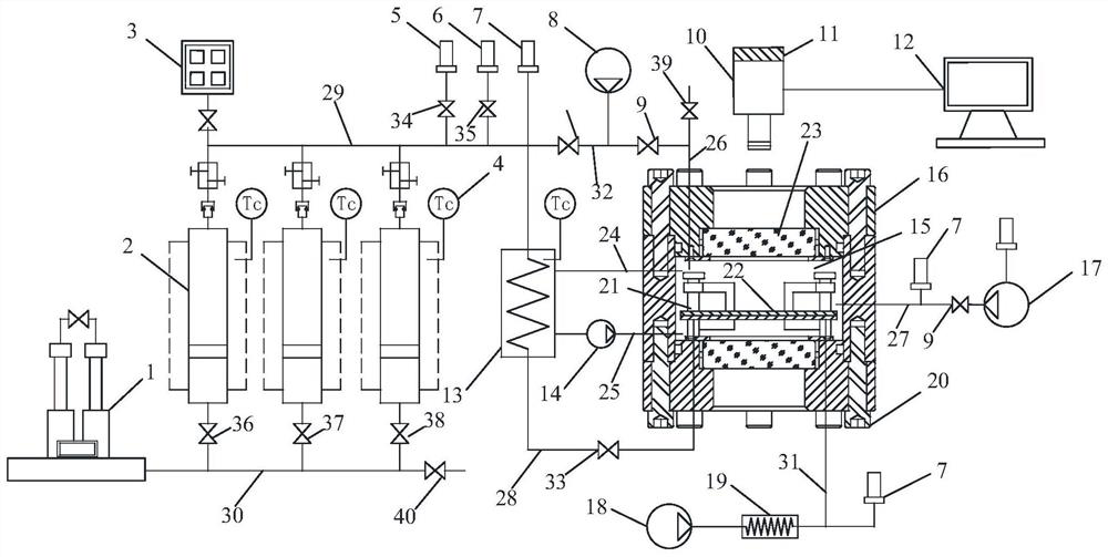
[0044] A microscopic visualization experimental method for high temperature and high pressure gas flooding in deep reservoirs, using a microscopic visualization experimental device, such as figure 1 As shown, it includes reservoir temperature and pressure coordinated control system, displacement response system, data acquisition and video recording system and auxiliary system. The main function of the reservoir temperature-pressure coordinated control system is to simulate the formation pressure and temperature of the rock formation in the real reservoir environment. The reservoir temperature and pressure coordinated control system includes a high-pressure sealing holder 16, on which a sapphire window 23 for easy observation is set, and a reservoir confining pressure ring cavity 15 is formed inside the high-pressure sealing holder 16 . The reservoir confining pressure ring cavity 15 is connected to the shell inlet of the high temperature heating vessel 13 through the fluid he...


PUM


Abstract

The invention discloses a deep oil reservoir high-temperature and high-pressure gas-displacing oil microcosmic visualization experiment method, which comprises the following steps of: installing a glass etching model for simulating a rock sample under an actual reservoir condition in a high-pressure sealed holder, and performing vacuumizing; injecting confining pressure liquid into a reservoir confining pressure annular cavity, and controlling the confining pressure through a confining pressure tracking pump; heating the confining pressure liquid in the reservoir confining pressure annular cavity through a high-temperature heating container; placing a glass etching model under a microscope; loading crude oil and a displacement fluid medium into a heating constant-temperature piston container, and adjusting a back pressure unit to a stratum simulation pressure; and carrying out a water and gas injection displacement experiment through a high-pressure injection pump and a gas pressurization system. The method can be used for simulating the oil-water-gas distribution state and fluid migration characteristics in a micro-nano pore structure, quantitatively characterizes the high-temperature and high-pressure water drive, gas drive and chemical drive microcosmic remaining oil starting mechanism, and has important guiding significance for judging the oil-water saturation distribution and size in the oil field reservoir development process.

Description

technical field [0001] The invention relates to the technical field of microscopic displacement, in particular to a microscopic visualization experiment method for high-temperature and high-pressure gas flooding in deep oil reservoirs. Background technique [0002] With more and more exploration and development activities in deeper and more complex formations around the world, it is becoming more and more difficult to tap the remaining oil potential under high temperature and high pressure conditions in deep formations. Especially when the oilfield enters the period of production decline in the high water-cut development stage, the mining potential target is gradually shifting from the large connected remaining oil to the highly dispersed, localized and relatively enriched areas. Due to unclear understanding of the microcosmic occurrence and distribution of remaining oil, Seriously hindered the remaining oil potential in the next step. Therefore, it is particularly importan...

Claims


Application Information

Patent Timeline
Patent Type & Authority Applications(China)
IPC IPC(8): G01N13/04G01N15/08G01M10/00H04N5/76
CPCG01N13/04G01N15/08G01M10/00H04N5/76
Inventor 李蕾苏玉亮郝永卯张雪王文东付金刚高小刚
Owner CHINA UNIV OF PETROLEUM (EAST CHINA)
Why Eureka
Try Eureka