Welding surface detection device based on machine vision and detection method thereof

A detection device and machine vision technology, applied in the direction of optical testing flaws/defects, etc., can solve the problems of cumbersome steps, inability to achieve the detection effect of the welding surface, etc., and achieve the effect of ensuring the clamping effect, improving the welding range, and improving the range of activities.

Pending Publication Date: 2021-05-28
YELLOW RIVER CONSERVANCY TECHN INST
View PDF0 Cites 1 Cited by
  • Summary
  • Abstract
  • Description
  • Claims
  • Application Information

AI Technical Summary

Problems solved by technology

[0004] This application improves the existing technology. In the prior art, after the welding process of the workpiece, it is often necessary to detect its welded part through a visual inspection device to judge whether it is a cost product or a defective product. However, the commonly used The method is that after the welding is completed, the inspection can only be carried out after manual transfer to the inspection line. The steps are cumbersome, and the inspection effect of the welding surface cannot be achieved when the material is clamped. Therefore, a welding surface inspection based on machine vision is proposed. Device and detection method thereof

Method used


Image

  • Welding surface detection device based on machine vision and detection method thereof
  • Welding surface detection device based on machine vision and detection method thereof
  • Welding surface detection device based on machine vision and detection method thereof

Examples


Embodiment Construction

[0038] The following will clearly and completely describe the technical solutions in the embodiments of the present invention with reference to the accompanying drawings in the embodiments of the present invention. Obviously, the described embodiments are only some, not all, embodiments of the present invention. Based on the embodiments of the present invention, all other embodiments obtained by persons of ordinary skill in the art without making creative efforts belong to the protection scope of the present invention.

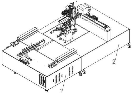
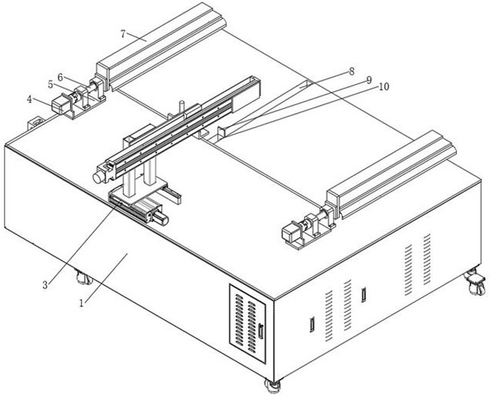
[0039] see Figure 1-8 , in an embodiment of the present invention, a machine vision-based welding surface detection device and detection method thereof, comprising a bottom box one 1, one side of the bottom box one 1 is fixedly connected with a bottom box two 2, and a bottom box one on the top of the bottom box one 1 The side is fixedly installed with a welding structure 3, and the other side of the top of the bottom box-1 is provided with three slideways-8, ...


PUM


Abstract

The invention discloses a welding surface detection device based on machine vision and a detection method thereof. The welding surface detection device comprises a first bottom box, a second bottom box is fixedly connected to one side of the first bottom box, a welding structure is fixedly installed on one side of the top of the first bottom box, and three first sliding ways are formed in the other side of the top of the first bottom box; two motor mounting plates and two cover frames are fixedly mounted at the top of the first bottom box, a first driving motor is fixedly mounted at the top of each motor mounting plate, and a first threaded rod is fixedly connected to the driving end of each first driving motor. According to the welding surface detection device based on machine vision and the detection method thereof, automatic discharging of welded materials is achieved, welded workpieces are made to be away from a welding area, meanwhile, material clamping, namely welding surface detection of the workpieces is achieved, direct classified transportation is achieved after detection is completed, manual transfer is not needed, welding, unloading and detection are completed in one step, the process flow is reduced, and then the working efficiency is improved.

Description

technical field [0001] The invention relates to the field of welding, in particular to a machine vision-based welding surface detection device and a detection method thereof. Background technique [0002] Welding, also known as welding, is a manufacturing process and technique that uses heat, high temperature, or pressure to join metal or other thermoplastic materials such as plastics. There are many sources of energy for modern welding, including gas flames, electric arcs, lasers, electron beams, friction, and ultrasound. In addition to its use in factories, welding can also be performed in a variety of environments, such as in the field, underwater and in space. Welding, wherever it occurs, can pose a hazard to the operator, so proper precautions must be taken when welding. Possible injuries caused by welding to the human body include burns, electric shock, visual impairment, inhalation of toxic gases, and excessive ultraviolet radiation. [0003] Machine vision is a ra...

Claims


Application Information

Patent Timeline
Patent Type & Authority Applications(China)
IPC IPC(8): G01N21/88
CPCG01N21/88
Inventor 王海博曹丽芳张研王艳凤黄莉刘小红王兵维史龙飞杜金博
Owner YELLOW RIVER CONSERVANCY TECHN INST
Why Eureka
Try Eureka