Nuclear battery and method for providing electric energy
A technology of nuclear battery and electric energy, applied in the field of nuclear battery, can solve the problems of semiconductor crystal damage and efficiency drop, etc.
Active Publication Date: 2021-05-28
JILIN UNIV
14 Cites 0 Cited by
AI-Extracted Technical Summary
Problems solved by technology
The β volt effect nuclear battery uses the energy of β particles to form electron-hole pairs in the PN junction region of the semiconductor. Under the built-in electric field, the electrons flow to the N region, and the holes flow to the P region to...
Method used
In some embodiments, transducer 3 Schottky structure electrode materials have multiple, can be the NiO that Ni-63 is made as wide bandgap oxide layer 12, the radioactivity of wide bandgap oxide layer 12 self can be The self-absorption of the source is reduced, so that the wide bandgap oxide layer 12 is both a radiation source and an electrode, further improving battery power. The transducer 3 is connected to the electrode plate 8 through the wide bandgap oxide layer 12 and the inert metal layers 13A and 13B to facilitate the extraction of current.
[0025] The liquid ionization medium area 2 is sleeved outside the radioactive source 1, and the liquid ionization medium area 2 is an electrolyte liquid. The liquid ionization medium area 2 is configured to receive high-energy particles generated by the radioactive source 1 and absorb part of the kinetic energy to generate charged free radicals in the solution. The use of liquid electrolyte not only greatly reduces the damage caused by radioactive source 1 to semiconductor radiation, but also utilizes the kinetic energy of high-energy particles to further generate charged particles and improve energy use efficiency. In some embodiments, the free radicals in the liquid ionization medium area 2 are mainly provided by water molecules, so most aqueous solutions or pure water can be used as the medium in the liquid ionization medium area 2 . Preferably, the liquid ionization medium zone 2 is a KOH solution.
[0037] In some embodiments, since the surface of one or more of the inert metal layer 13A, 13B and the wide bandgap oxide layer 12 is a nanoporous structure, a plasma electric field will be formed in the nanopore. In some...
Abstract
The invention relates to a nuclear battery. The nuclear battery comprises a radioactive source, a liquid ionization medium area arranged outside the radioactive source in a sleeving manner and configured to receive part of kinetic energy of high-energy particles generated by the radioactive source and enable a solution to generate charged free radicals, a transducer arranged outside the liquid ionization medium area in a sleeving manner and configured to receive high-energy particles and charged free radicals generated by the liquid ionization medium area and convert the high-energy particles and the charged free radicals into electric energy, a shielding layer wrapping the radioactive source and the liquid ionization medium area, two electrode plates arranged on the upper side and the lower side of the nuclear battery and respectively coupled to the anode and the cathode of the transducer, and an energy storage unit arranged outside the energy converter in a sleeving mode and configured to store electric energy generated by the energy converter, wherin an anode and a cathode of the energy storage unit are coupled to the anode and the cathode of the energy converter. The application further comprises a method of providing electrical energy.
Application Domain
Radiation electrical energy
Technology Topic
Nuclear physicsElectrical battery +9
Image
Examples
- Experimental program(1)
Example Embodiment
[0020]In order to make the objects, technical solutions, and advantages of the present invention more clearly, the technical solutions in the embodiments of the present invention will be described in contemplation in the embodiments of the present invention, and will be described, and the embodiments described in the embodiments of the present invention will be described. It is a part of the embodiments of the present invention, not all of the embodiments. Based on the embodiments of the present invention, there are all other embodiments obtained without making creative labor without making creative labor premises.
[0021]In the following detailed description, various instructions for explaining the specific embodiments of the present application can be seen as part of the present application. In the drawings, similar reference numerals are marked in different drawings. The various specific embodiments of the present application have been described in sufficient detailed description in the following, so that ordinary skill in the art will implement the technical solutions of the present application. It should be understood that other embodiments may be utilized or changed in structures, logic, or electrical changes to the embodiments of the present application.
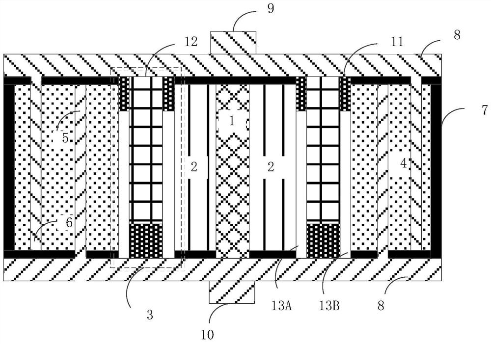
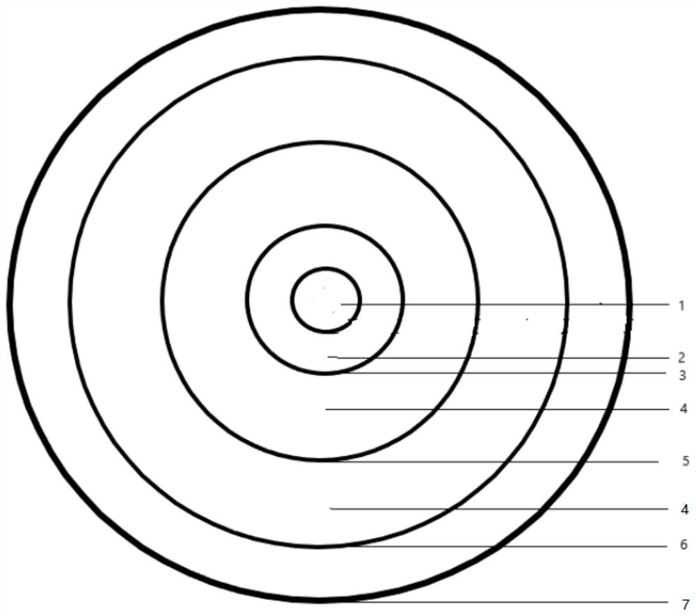
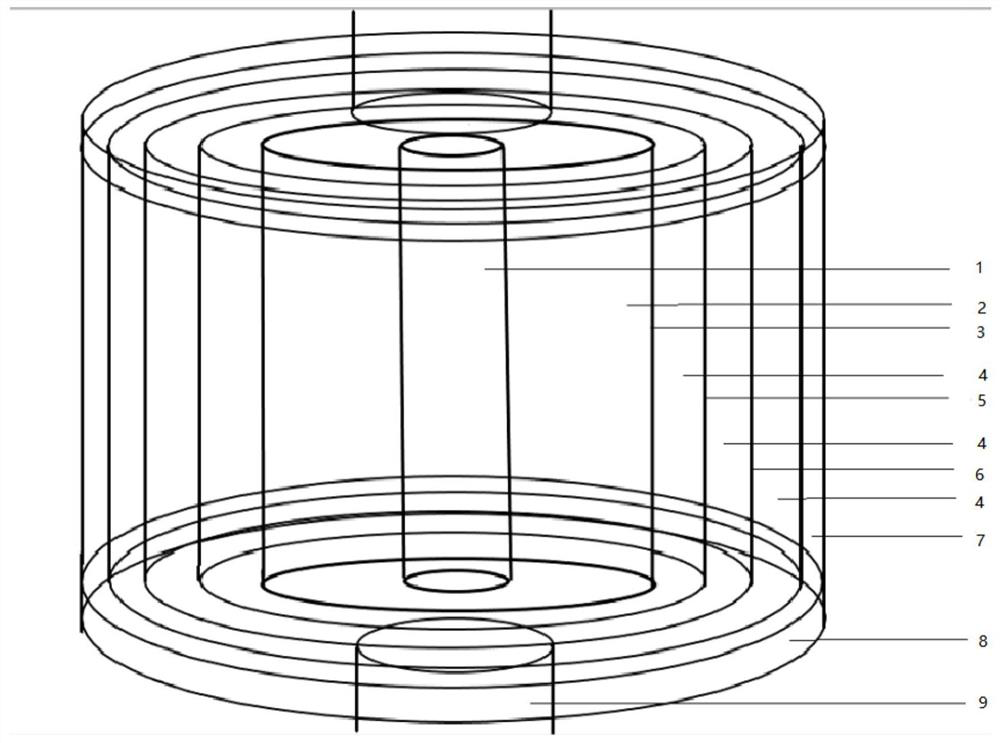
[0022]figure 1 It is an integral structure side view according to an embodiment of the present invention.figure 2 It is a top plan view of an embodiment of an embodiment of the present invention.image 3 It is an integral structure perspective view according to an embodiment of the present invention. Bonded belowFigure 1-3Explain the structure and working principle of the present application.
[0023]The nuclear battery according to the present application includes: radiation source 1, liquid ionizing medium region 2, transducer 3, liquid storage medium region 4, first storage electrode 5, second energy storage electrode 6, shielding layer 7, electrode plate (Nuclear battery electrode) 8, metal wire 9, metal wire 10, insulating layer 11, broadband gap oxide layer (second power electrode) 12, first inert metal layer (first power electrode) 13A and a second inert metal layer (First power electrode) 13b.
[0024]In some embodiments, the radiation source 1 is a cylindrical shape. The radiation source 1 is fitted at the center surface of the cylindrical electrode plate 8. In some embodiments, the selection principle of the radiation source 1 is to discharge the ray type as a single as possible, and the half-life of the radioactive substance cannot be too short, more than a few years. The radiation source 1 can be an alpha radiation source or a β radiation source, the alpha radiation source is 镅-241, -239, uranium-238 or 锔 -244, etc .; β radiation source is carbon-14, strontium-90, nickel-63 , 铊 -204 or 钷 -147, etc. In some embodiments, the radiation source 1 can be replaced by themselves. In some embodiments, the bottom of the radiation source 1 further includes a movable shield layer (not shown), the movable shielding layer to which the electrode plate 8 is active. After removing the movable shield, the radiation source 1 can be taken out to replace it. After replacing the radiation source 1, the active shielding layer can be replaced to further reduce the radiation of radiation.
[0025]The liquid ionization medium region 2 is arranged outside the radiation source 1, and the liquid ionization medium region 2 is an electrolyte liquid. The liquid ionization medium region 2 is configured to receive high energy particles generated by the radiation source 1 and absorb partial movement to produce a solution to charge free radical. With liquid electrolyte, not only the damage caused by radio source 1 on semiconductor radiation, but also uses high energy particle kinetic energy to further produce charged particles to improve energy efficiency. In some embodiments, the free radicals of the liquid ionizing medium region 2 are mainly provided by water molecules, so most of the aqueous solution or pure water can be used as a liquid ionization medium region 2 medium. Preferably, the liquid ionizing medium region 2 is a KOH solution.
[0026]The transducer 3 is arranged outside the liquid ionization medium region 2, and the transducer 3 is a Schottky device, which is converted to the charged free radicals generated by the high energy particles and the liquid ionization medium region 2 and converted into electrical energy. The transducer 3 includes: an insulating layer 11, a wide band gap oxide layer 12, a first and second inert metal layers 13a, and 13b. Such asfigure 1 As shown, the transducer 3 includes an inert metal layer 13a and 13b disposed on both sides, a broadband gap oxide layer 12 in the middle of the two ineraces 13a and 13b. An insulating layer 11 is provided at the bottom of the inert metal layers 13a and 13b and the bottom of the wide band gap oxide layer 12. The inert metal layers 13a and 13b form a Schottky contact with the broadband gap oxide layer 12, and the internal field is formed inside. At the same time, the inert metal layers 13a and 13b and the wide band gap oxide layer 12 are also configured as the conductive electrode of the transducer 3, that is, the first power electrode and the second power electrode), respectively connected to the lower portion and the upper electrode plate 8, respectively. In some embodiments, one or more of the inert metal layers 13a, 13b, or the broadband gap oxide layer 12 are nanoporous structures. In some embodiments, the broadband gap oxide layer 12 has radioactivity. In some embodiments, the inert metal layers 13a and 13b are disposed as a transducer 3 anode, and the wide band gap oxide layer 12 is disposed as a transducer 3 cathode. In some embodiments, the transducer 3 can be replaced.
[0027]In some embodiments, the transducer 3 Schottky structural electrode material has a variety of, such as the broadband gap oxide layer 12 may be NiO made from Ni-63, and the radioactivity of the wide band gap oxide layer 12 can reduce the source. Self-absorbing, such broadband gap oxide layer 12 is both radioactive sources and electrodes, further increasing battery power. The transducer 3 is connected to the electrode plate 8 by a broadband gap oxide layer 12 and inert metal layers 13a and 13b to facilitate export current.
[0028]In some embodiments, the radiation source 1, the liquid ionization medium region 2, and the transducer 3 together constitute a power generation unit of the nucleate cell.
[0029]The energy storage unit is arranged exterior to the transducer 3, configured to store the power release of the transducer 3 release. The energy storage unit includes: a liquid storage medium region 4, a first energy storage electrode 5, and a second storage electrode 6. The first energy storage electrode 5 and the second storage electrode 6 are disposed in the liquid energy storage medium region 4, such asfigure 1 Or 3, the first storage electrode 5 and the second storage electrode 6 divide the liquid energy storage medium zone 4 into three portions. Among them, the liquid storage medium region 4 is an electrolyte liquid. In some embodiments, the liquid energy storage medium region 4 has a TEA · BF4 (tetrafluororate tetraethyl ammonium). In some embodiments, the first reservoir electrode 5 is configured to be a positive electrode, and the second storage electrode 6 is configured to be a negative electrode. In some real-time examples, the material of the first storage electrode 5 and the second energy storage electrode 6 is copper or aluminum. Preferably, the first energy storage electrode 5, the second storage electrode 6 is a nano metal oxide electrode.
[0030]The shield layer 7 is arranged outside the liquid storage medium region 4, and is disposed at the top and bottom of the radiation source 1, the liquid ionization medium region 2, the liquid energy storage medium region 4, and the top and second of the first storage electrode 5. The bottom of the energy storage electrode 6. The shield 7 is a high molecule plastic of heavy metals or doped heavy metals. The shielding layer 7 is a shielding layer is a battery case having a secondary X-ray and gamma rays generated inside the shielded layer shield the battery, which is heavy metal, a polymer plastic or doped weight metal to increase the gamma ray shielding capability. The shield 7 encapsulates the inside of the battery to reduce radiation, and supports the fixing electrode plate 8 and the four electrodes.
[0031]The electrode plate 8 is disposed on both sides of the battery, and the upper / lower electrode plate 8 is respectively coupled to the cathode / anode of the transducer 3 and / or the energy storage unit, respectively, respectively, and the cathode and anode of the nucleate battery are respectively. The electrode plate 8 is an aluminum plate or a copper plate. In some embodiments, the upper / lower electrode plate 8 is connected to the metal wire 9 and the metal wire 10, the metal wire 9, and the metal conductor 10 are configured as the cathode and an anode connected to the outside. In some embodiments, the metal conductor 9 and the metal wire 10 are aluminum wire or copper wire.
[0032]The nuclear battery, the radiation source 1, the liquid ionization medium region 2, and the transducer 3 constitute a battery power generating unit, a liquid storage medium region 4, a first storage electrode 5, and a second energy storage electrode 6 constitute a battery energy. unit. In some embodiments, the number of units can be increased down according to the actual demand, to achieve different application scenarios. Infigure 2 Take the example,figure 2 In the structure, from the inside to the outside of the radial source 1, the liquid ionization medium region 2, the transducer 3, the liquid storage medium region 4, the first energy storage electrode 5, and the second storage electrode 6, i.e., a power generation unit jacket. Set the energy unit.
[0033]In some embodiments, the power generating unit may further include a second power generation unit set, and further include an energy storage unit outside of the second power generation unit. In some embodiments, the center of the nuclear battery is an energy storage unit, and its outer casing is a power generation unit, and a second storage unit is provided in the extension of the power generation unit. In some embodiments, the first storage unit further includes a second storage unit. Similar structures are included in this application, they are not described herein.
[0034]It should be noted that when, for example, the second power generation unit is set outside the first power generation unit, the second radiation source of the second power generating unit may directly contact the first power generation unit of the first power generation unit, for the first change. It can cause damage. In this case, it may further include a third liquid state zone disposed between the second radiation source and the first transducer, and the beneficial effects of the present application can be obtained.
[0035]The nuclear battery working principle is: Radiation source 1 emits particles such as α or β, and high energy particles are hit by water molecules in solution. The kinetic energy of its high energy particles is absorbed, producing a large number of free radicals, and then high energy particles impact Transducer 3 (particle kinetic energy is greater than semiconductor electrons and cavitation) and ionizing the free electron and holes, the broadband gap oxide layer 12 and inert metal layers 13a and 13b form a barrier generating electric field, making the generated electronics and empty The point is directed in which the current is generated. These charged particles are then derived by the positive electrode 10 and the negative electrode 9, and the external load can form a stable DC current.
[0036]In some embodiments, the broadband gap oxide layer 12 can form Schottky, holes, and electrons to the inert metal layers 13a and 13b, electronically movable, electron to broadband gap oxide layer 12, holes Move to the inert metal layers 13a and 13b. During this process, the hole accumulated at the inert metal layer 13a will further peele the negative radicals from the solution to obtain more charged particles. The charge free radical generated in the water not only protects the transducer 3, but also participates in conductive, further enhances the efficiency of nuclear batteries.
[0037]In some embodiments, since the surface of the inert metal layer 13a, 13b, and the width gap oxide layer 12 is a nanoporous structure, a plasma electric field is formed in the nanoporous structure. In some embodiments, the plasma electric field is the same as that of the internal electric field, increasing the reaction site (i.e., the nanoporous electric field) during the electrical energy conversion, and further increase the conductivity efficiency. In some embodiments, the plasma electric field is opposite to the inner electric field direction, and the direction of movement of electrons and holes depends on electric fields with higher electric field strength. In some embodiments, the thickness of the inert metal layers 13a, 13b is small, and the composite of negative radicals and holes is reduced, and the carrier concentration is further improved.
[0038]In some embodiments, the broadband gap oxide layer 12 can be both radiosensive sources and transducers, reducing high-energy particles from absorbing while simultaneous radiation, and further producing electronics and holes, improve nuclear Battery power generation efficiency.
[0039]The electric energy generated by the generated power generating unit can be charged by the first storage electrode 5 and the second storage electrode 6 while being transmitted by the electrode plate. The liquid storage medium region 4 is an electrolyte solution, and the first storage electrode 5 is a nano metal oxide positive electrode plate, and the second energy storage electrode 6 is a metal oxide negative electrode plate, and the energy storage unit forms a similar capacitor structure to achieve energy. the goal of.
[0040]In some embodiments, according to the output voltage current demand at the time of the actual application, the amount of radioactive source dose, the number of charge collecting units can be adjusted to meet the specific parameter requirements.
[0041]The theoretical energy utilization of the present invention is higher than that of the ordinary radiation volt effect nuclear battery, which greatly increases the power and radiation particle kinetic utilization, advance storage electrical energy, and helps direct use and power of electrical energy and significantly, and use liquid electrolytes, not only avoidance The efficiency decreased due to semiconductor radiation damage, but also utilizes radiation energy, increasing energy efficiency, and the broadband gap layer 12 can be Ni-63, nickel oxide electrodes made of Ni-63, which is both radiation sources and electrodes to further improve battery power. . And can flexibly increase or decrease the power generation unit according to the design requirements, the number of energy storage units. It is conducive to the miniaturization of nuclear batteries to increase the battery power and capacity, while replacing the transducer or radioactive source, which is conducive to the later maintenance, cost savings is a new radioactive energy utilization idea, which has better research and application. The foreground, while the battery structure design avoids the tap structure of the battery to help reduce internal resistance, increase capacity and charging speed.
[0042]The present invention will be further described below with reference to the accompanying drawings and specific examples.
[0043]In some embodiments, the radiation source 1 is selected to be Y-90, and the maximum energy of the emitted β particles is 2.2839 MeV, the average β particle energy is 935 keV, the specific activity is 543753.50CI / g, the specific power is 601 W / g. The β particles can be ionized from the water molecules through the liquid ionization medium region 2 to form a number of stable free radicals. When the high energy particles are broadband oxide layer 12 (NiO) by the inert metal layer 13a (Pt) and the surface nanopore structure, an electronic hole pair is generated inside the nanopore NiO. The hole generated in NiO moves to the PT / liquid interface, making Pt of both sides of the inert metal layers 13a and 13b into a positive electrode. Electrons are transmitted to the electrode plate 8 by nanopore NiO, and NIO becomes a negative electrode. At the same time, the inert metal layer PT can protect NiO under electrolyte of high pH.
[0044]The reason why the above phenomenon is, the principle is that the PT / NiO structure forms an internal construction electric field, and the N-type NIO layer is spread from the Fermi energy level diffuses from NIO to PT, and the direction of hole movement is opposite, the electric field direction from NIO Point to PT. The radiation will generate ionic in the surface of the PT / NiO, and the ion oscillation generates the direction of the electric field and the built-in electric field, and the hole flows to PT under the action of the composite electric field (plasma electric field and built-in electric field). The flow to NIO, so that the carrier can be separated. In some embodiments, the holes accumulated at the pip of the PT can further suck the negative radical radicals in the water to attract negative radicals to the surface of the PT electrode and flow to NiO under the composite electric field.
[0045]The surface particle output power is approximately 246.5 mW / cm by adjusting the appropriate thickness.2The percentage of the electrolytic solution region can be estimated by the MC simulation, so that the particle reaches the replacement device kinetic energy does not cause radiation damage (lower than NIO), and finally obtains the output voltage of 24.2V, and the output power density is 106.7. MW / cm2The ultimate efficiency is 43.3%. Such power and limit conversion efficiency are superior to ordinary radiation volts effect nuclear batteries.
[0046]In some embodiments, the NIO can replace the radiation source Ni63, further utilize the Schottky structure of the transducer 3, generate more electronic holes, separating more charges under electric field, simultaneous incident α or β radiation can be scattered and reflected by our nanopore structure, which utilizes ray energy, which means that the battery structure composed of PT / nanopore NiO and electrolyte will obtain more energy.
[0047]The energy storage unit is charged by exporting the charge, the excess charge in the surface of the first storage electrode 5 and the second energy storage electrode 6 and the liquid energy storage medium region 4 contact position, and a solution is applied between the two electrodes. The positive and negative ions of the decomposed voltage (i.e., the charging) electrolyte will move to different two poles in the electric field, and two charge layers are formed on the surface of the two poles, which can be effectively stored. Such capacitive effects are smaller in the tight charge layer, there is a better capacity, and there is a high breakdown voltage, the battery charge is not accompanied by chemical changes, the electric energy is directly utilized, there is a fast charging time, the service life is guaranteed, saving Energy, green and environmentally friendly features.
[0048]This application relates to a nuclear battery. It is provided with a liquid ionization medium zone between the radiation and transducers, and the transducer is protected on one aspect, and more conductive particles are provided on the one hand. Since the transducer is damaged, the more energy of the alpha source can be used as the radiation source to obtain greater energy. At the same time, the increase in conductive particles can also improve nuclear battery efficiency. The use of nanopore structures can be increased by the use of nanopore structures to increase efficiency. The wide-bandkeeration can also be replaced with a radioactive metal oxide to further increase the battery power, and reduce the derived self-absorption. The present application program also proposes the energy storage unit structure, which can store excess power, greatly improve the utilization of nuclear batteries.
[0049]In some embodiments, the broadband gap oxide layer 12 can be a p-type semiconductor (e.g., NiO doped B). In this case, the plasma electric field is the same as the internal construction of the built-in electric field, and the superimposed composite electric field can be better separated from electronics and holes to increase the carrier mobility.
[0050]Figure 4 It is a flow chart of providing an electrical energy method in accordance with one embodiment of the present invention.
[0051]The method includes:
[0052]Step 401: Receive partial kinetic energy of the high energy particles produced in the first radiation source and produces a charge free radical.
[0053]Step 402: Receive the charged free radicals generated by the high energy particles and the first liquid state zone and converted to electrical energy at the first transducer.
[0054]Step 403: The electrical energy generated by the first transducer is stored in the first storage unit by connecting the two electrode plates connected to the first transducer.
[0055]The above embodiments are merely illustrative of the invention, which is not intended to limit the invention, and various modifications and variations can be made without departing from the scope of the invention, and therefore, all The equivalent technical solution should also belong to the scope of the disclosure of the present invention.
PUM


Description & Claims & Application Information
We can also present the details of the Description, Claims and Application information to help users get a comprehensive understanding of the technical details of the patent, such as background art, summary of invention, brief description of drawings, description of embodiments, and other original content. On the other hand, users can also determine the specific scope of protection of the technology through the list of claims; as well as understand the changes in the life cycle of the technology with the presentation of the patent timeline. Login to view more.