Inductive coupling type direct-current fault current limiter and control method thereof

A DC fault and inductive coupling technology, which is applied to emergency protection circuit devices, electrical components, circuit devices, etc. for limiting overcurrent/overvoltage, can solve the problem of increasing fault current clearing time, rapid DC voltage drop, and endangering DC power grids and other problems to achieve the effect of shortening the cleaning time

Active Publication Date: 2021-05-28
TIANJIN UNIV
View PDF6 Cites 3 Cited by
  • Summary
  • Abstract
  • Description
  • Claims
  • Application Information

AI Technical Summary

Problems solved by technology

In the low-voltage DC distribution network, it is usually required to remove the fault within a few milliseconds after the fault occurs, but the traditional mechanical circuit breaker cannot meet this requirement. Therefore, it is necessary to install a current limiter in the line to limit the current The rate of rise and magnitude of the current can provide enough time for the circuit breaker to isolate the fault
Traditional current limiters usually use the method of directly connecting the inductor in series to the line to limit the current. Although this method can limit the current rise rate, when the system is running normally, the series connection of the inductor in the line will affect the system performance. Dynamic response characteristics, also increases the clearing time of the fault current
When a short-circuit fault occurs in the DC system, due to the discharge of the capacitor, the fault current rises rapidly and the DC voltage drops rapidly, seriously endangering the entire DC grid

Method used


Image

  • Inductive coupling type direct-current fault current limiter and control method thereof
  • Inductive coupling type direct-current fault current limiter and control method thereof
  • Inductive coupling type direct-current fault current limiter and control method thereof

Examples


Embodiment Construction

[0023] The technical solutions of the present invention will be described in detail below in conjunction with the accompanying drawings and embodiments.

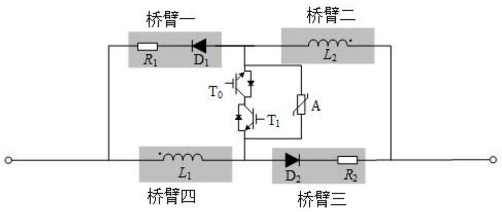
[0024] Such as figure 1 As shown, the topological structure diagram of the inductively coupled DC fault current limiter of the present invention. The topology structure is an H-bridge structure composed of bridge arm one to bridge arm four. Among them: bridge arm one is composed of the first diode group D 1 with the first resistor R 1 Constituted in series; bridge arm three is composed of the second diode group D 2 with the second resistor R 2 connected in series; bridge arm 4 and bridge arm 2 are respectively composed of the first coupling inductor L 1 with the second coupled inductor L 2 Formed, the inductance values ​​of the two coupled inductors are equal. The dotted side of the coupled inductor is shown in the figure.

[0025] An IGBT group is connected in series between the first and second connection points of...


PUM


Abstract

The invention discloses an inductive coupling type direct current fault current limiter and a control method thereof. The inductive coupling type direct current fault current limiter structurally comprises a first bridge arm, a second bridge arm, a third bridge arm, a fourth bridge arm and an H bridge circuit formed by the first bridge arm, the second bridge arm, the third bridge arm and the fourth bridge arm, wherein the first bridge arm and the second bridge arm are connected in series, the fourth bridge arm and the third bridge arm are connected in series, and a series branch formed by the first bridge arm and the second bridge arm is connected with a series branch formed by the third bridge arm and the fourth bridge arm in parallel. The control method for the inductive coupling type direct-current fault current limiter comprises the steps: initializing, and when a fault signal is detected, turning off an IGBT set, so that current consumption of an inductance loop is made to be zero; triggering the IGBT set again; and recovering a current limiter to prepare for the next fault. Compared with the prior art, the inductive coupling type direct current fault current limiter is used for a low-voltage flexible direct-current power distribution network, and has the advantages that 1) during normal operation, adverse effects on transient response characteristics and operation stability of a direct-current system are avoided, and 2) after direct current fault, the rapid rising of the fault current can be effectively limited, and sufficient action time is created for protection and fault isolation.

Description

technical field [0001] The invention relates to the field of multi-terminal flexible DC distribution network, in particular to a DC fault current limiter topology and control strategy based on the cooperation of coupled inductors and lightning arresters. Background technique [0002] In recent years, with the increase in the number of distributed power sources and new energy sources, the low-voltage DC distribution network has the advantages of small line loss, high power supply reliability and easy access to distributed power sources and energy storage devices. Therefore, based on the voltage source type The flexible DC power distribution system of the converter (voltage source converter, VSC) has become an important topic of current research. However, when a bipolar short-circuit fault occurs in a flexible DC power distribution system based on a VSC converter, the capacitor in the converter will discharge to the fault point, and the discharge current will rise rapidly and ...

Claims


Application Information

Patent Timeline
Patent Type & Authority Applications(China)
IPC IPC(8): H02H9/02H02H9/04
CPCH02H9/02H02H9/04
Inventor 李斌贾涵茹何佳伟
Owner TIANJIN UNIV
Why Eureka
Try Eureka