Bidirectional DCDC power conversion circuit
A technology for converting circuits and power, applied in the field of electronics, can solve problems such as increased heat generation, reduced product reliability, and increased product cost, and achieve the effects of suppressing peak voltage, improving reliability, and reducing difficulty in model selection
- Summary
- Abstract
- Description
- Claims
- Application Information
AI Technical Summary
Problems solved by technology
Method used
Image

Examples
Embodiment 1
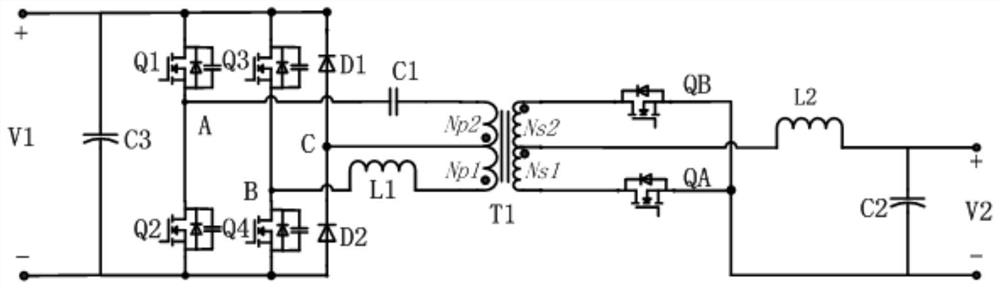
[0089] Please refer to figure 1 , a bidirectional DCDC power conversion circuit, comprising a full bridge rectifier circuit, a transformer, a first diode, a second diode, a first capacitor, a first inductor and a switch circuit;
[0090] The first end of the full-bridge rectifier circuit is respectively connected to the positive pole of the preset first input and output terminal and the negative pole of the first diode, and the second terminal is respectively connected to the negative pole of the preset first input and output terminal and the second The anode of the diode is connected, the third end is connected to one end of the first capacitor, and the fourth end is connected to one end of the first inductance; wherein, the third end is figure 1 In point A, the fourth end is figure 1 Point B in the first input and output terminal; a filter capacitor C3 is connected in parallel at both ends of the first input and output terminal; the first capacitor is a DC blocking capacito...
Embodiment 2
[0096]The difference between this embodiment and Embodiment 1 is that this embodiment specifically defines the switch circuit and its connection relationship;
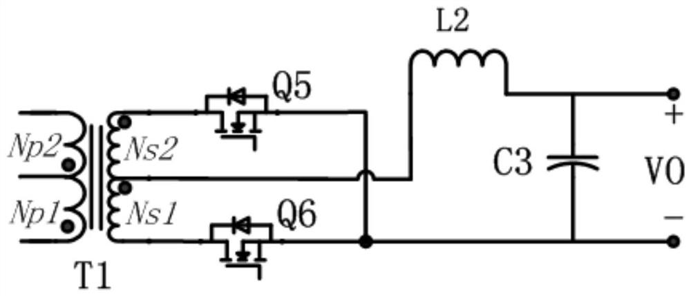
[0097] Please refer to figure 2 , the switch circuit includes a fifth MOS transistor and a sixth MOS transistor;
[0098] The secondary coil of the transformer is divided into a first coil Ns1 and a second coil Ns2 through a secondary tap; the end of Ns2 away from the tap is the third end of the transformer, and the end of Ns1 away from the tap is the third end of the transformer. Four terminals; the number of turns of Ns1 is the same as that of Ns2;
[0099] Specifically, the secondary tap of the transformer is connected to the other end of the second inductor; the third end of the transformer is connected to the drain of the fifth MOS transistor, and the fourth end is connected to the drain of the sixth MOS transistor. The drain is connected; the source of the fifth MOS transistor and the source of the sixth MOS t...
Embodiment 3
[0106] The difference between this embodiment and Embodiment 1 or 2 is that this embodiment also includes a logic circuit and an enabling control circuit;
[0107] controlling the switch circuit on the secondary side of the transformer through the logic control circuit and the enable control circuit;
[0108] Specifically, the logic control circuit includes a first logic circuit and a second logic circuit; the input terminals of the first logic circuit are respectively connected to the gate of the first MOS transistor and the gate of the fourth MOS transistor, and the output terminal is connected with the first control terminal of the switch circuit; the input terminal of the second logic circuit is respectively connected with the gate of the second MOS transistor and the gate of the third MOS transistor, and the output terminal is connected with the gate of the switch circuit The second control terminal is connected; the output terminal of the enabling control circuit is resp...
PUM
 Abstract
Description
Claims
Application Information
 - R&D
- Intellectual Property
- Life Sciences
- Materials
- Tech Scout
- Unparalleled Data Quality
- Higher Quality Content
- 60% Fewer Hallucinations
Browse by: Latest US Patents, China's latest patents, Technical Efficacy Thesaurus, Application Domain, Technology Topic, Popular Technical Reports.
© 2025 PatSnap. All rights reserved.Legal|Privacy policy|Modern Slavery Act Transparency Statement|Sitemap|About US| Contact US: help@patsnap.com