Electromagnetic rotary vibration energy collector

A vibration energy harvesting, electromagnetic technology, applied in the direction of generator/motor, piezoelectric effect/electrostrictive or magnetostrictive motor, electrical components, etc., can solve the problem of increasing the resonance frequency of the structure, small displacement, and failure of the acquisition structure And other issues

Active Publication Date: 2021-05-28
TIANJIN UNIV
View PDF12 Cites 1 Cited by
  • Summary
  • Abstract
  • Description
  • Claims
  • Application Information

AI Technical Summary

Problems solved by technology

[0004] The existing electromagnetic rotation energy harvesting technology mainly has the following problems, the magnetic levitation vibration energy harvester, the interference signals such as friction, collision and noise that exist during the movement of the levitation body will reduce the reliability of the sensor signal, and in addition, when the train runs at a high speed, Suspended objects are subjected to a large centrifugal force, causing them to be thrown to the outer end, resulting in the failure of the collection structure; the cantilever beam vibration energy harvester solves the problem of centrifugal force by means of the cantilever beam, and at the same time increases the resonance frequency of the structure, making it impossible to effectively pick up Train rotational energy; integrated rotational energy harvester, the relative displacement of magnet and coil is small, and the collection efficiency is low; stator-rotor split rotational energy harvester has low utilization rate of magnetic energy, and it is difficult to fix the stator in a rotating environment
In summary, electromagnetic rotary vibration energy harvesters generally have the problems of low magnetic field utilization and low power density.

Method used


Image

  • Electromagnetic rotary vibration energy collector
  • Electromagnetic rotary vibration energy collector
  • Electromagnetic rotary vibration energy collector

Examples


specific Embodiment approach

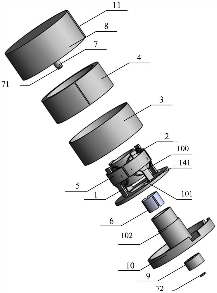
[0053] The coil device includes: a polyethylene insulating frame 1, and the outer side of the insulating frame 1 is a fan ring structure arranged in a 90° circular array, with a central angle of 60°, an outer diameter of 23.5mm, an inner diameter of 19mm, and a height of 6mm; in order to increase The number of turns of the coil winding 2, the insulating frame 1 arranges a rectangular support 100 up and down, the upper rectangular support 100 has a height of 2.5 mm, a width of 2.5 mm, and a thickness of 1.5 mm, and the lower rectangular support 100 has a height of 7 mm and a width of 2.5 mm. The thickness is 1.5 mm. In order to increase the stability of the lower rectangular support 100, an equilateral right-angled triangle structure with a side length of 2 mm and a thickness of 1.5 mm is arranged between the left and right sides of the lower rectangular support 100 and the insulating frame 1, wherein two Two adjacent lower side brackets are fixed with input pins 141; the inner ...


PUM


Abstract

The invention discloses an electromagnetic rotary vibration energy collector which comprises a coil device, a magnetic conductive device, a friction pendulum device, a bearing device and a management circuit. The coil device comprises an insulating frame and a coil winding, and the coil winding is wound on four supports of the insulating frame; the magnetic conductive device comprises a fixing ring, a magnetic ring, magnetic conductive sheets and a magnetic conductive ring, the magnetic ring is embedded into the inner side of the fixing ring, the magnetic conductive sheets are embedded into the outer sides of the four supports of the insulating frame, and the magnetic conductive ring is embedded into the inner side of the sleeve of the insulating frame; the bearing device comprises a rotating shaft, a shell, a bearing and a base, the rotating shaft is fixed in the center of the shell, the bearing is fixed inside a sleeve of the base, and the insulating frame is fixed outside the sleeve of the base; the friction pendulum device comprises a fan-shaped counter weight; the fan-shaped counter weight is fixed on the outer side of the shell; the management circuit comprises diodes and a voltage stabilizing capacitor, and the four diodes form a full-bridge rectification circuit with four pins. According to the invention, the interference signal is small and the power density is high.

Description

technical field [0001] The invention belongs to the technical field of energy collection, and in particular relates to an electromagnetic rotary vibration energy collector. Background technique [0002] In recent years, the rapid development of the passenger railway network and the continuous improvement of operating speed have posed huge challenges to the safe operation of trains and system reliability. Reliable on-line monitoring of high-speed trains using advanced technologies represented by wireless sensors can not only effectively evaluate the integrity of the bogie structure, but also prevent problems before they happen, and discover the potential for structural failures in old equipment in advance factor. However, as far as wireless sensor technology for vehicles is concerned, the power supply method is the main bottleneck restricting its large-scale application at this stage. The stable rotational energy existing in the running process of the train provides a space...

Claims


Application Information

Patent Timeline
Patent Type & Authority Applications(China)
IPC IPC(8): H02N2/18
CPCH02N2/188
Inventor 王炜王志霞
Owner TIANJIN UNIV
Why Eureka
Try Eureka