Piezoelectric micromechanical ultrasonic transducer with supporting column

A technology of ultrasonic transducers and support columns, applied in the field of micro-mechanics, can solve the problems of high power consumption, high operating voltage, limitations, etc., and achieve obvious piezoelectric effect, high receiving and transmitting sensitivity, and high acoustic energy conversion efficiency Effect

Inactive Publication Date: 2021-06-01
FUDAN UNIV
View PDF9 Cites 0 Cited by
  • Summary
  • Abstract
  • Description
  • Claims
  • Application Information

AI Technical Summary

Problems solved by technology

Compared with cMUTs, pMUTs based on piezoelectric materials such as AlN and ZnO and using bending vibration modes have outstanding advantages in low-power applications. However, since the piezoelectric coefficients of AlN and ZnO materials are much smaller than those of PZT materials, the electromechanical coupling coefficient of pMUTs , bandwidth, transmit and receive sensitivity and other performance are still far behind cMUT
At present, conventional cMUTs have high operating voltage and high power consumption, and need to maintain a high DC bias voltage (ranging from tens of volts to hundreds of volts) during operation
These reasons limit its application in portable, low power consumption and long-term online detection

Method used


Image

  • Piezoelectric micromechanical ultrasonic transducer with supporting column
  • Piezoelectric micromechanical ultrasonic transducer with supporting column
  • Piezoelectric micromechanical ultrasonic transducer with supporting column

Examples


Embodiment Construction

[0036] Hereinafter, the present invention will be described in more detail with reference to the accompanying drawings. In the various figures, the same elements are indicated with similar symbols. For the sake of clarity, various parts in the drawings have not been drawn to scale. In addition, some well-known parts may not be shown.

[0037] In the following, many specific details of the present invention are described, such as device structures, material size processing processes and techniques, for a clearer understanding of the present invention. However, the invention may be practiced without these specific details, as will be understood by those skilled in the art.

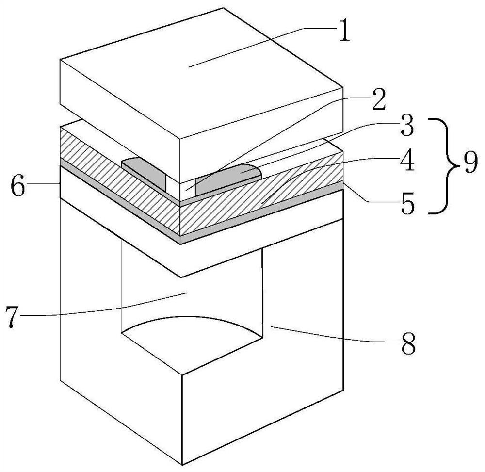
[0038] figure 1 A structural schematic diagram (three-dimensional cross-sectional view) of the piezoelectric micromachined ultrasonic transducer with supporting columns of the present invention is shown.

[0039] like figure 1 As shown, the structural diagram (three-dimensional cross-sectional view) of ...


PUM


Abstract

The invention belongs to the technical field of micromachinery, and particularly relates to a piezoelectric micromechanical ultrasonic transducer with a supporting column. The piezoelectric micromechanical ultrasonic transducer structurally comprises a vibration flat plate, the supporting column, an upper electrode, a piezoelectric material layer, a lower electrode, a structural layer, a cavity and a substrate which are arranged from top to bottom; displacement of the vibration flat plate and deformation of a piezoelectric vibration membrane are associated through the supporting column; the supporting column may be made of a linear elastic or rigid material; and one change of the piezoelectric micromechanical ultrasonic transducer is that the supporting column is made of a piezoelectric material, and a third electrode is introduced above the supporting column and used for exciting the piezoelectric supporting column. By means of the piezoelectric micromechanical ultrasonic transducer, the technical problems of low transmitting and receiving sensitivity and poor ultrasonic transmitting directivity caused by bending mode vibration of a piezoelectric micromechanical ultrasonic transducer in the prior art are solved, so that the application prospects of high-sensitivity detection and efficient ultrasonic transmitting are expanded, for example, the piezoelectric micromechanical ultrasonic transducer can be applied to three-dimensional real-time ultrasonic imaging.

Description

technical field [0001] The invention belongs to the technical field of micro-machines, and in particular relates to a micro-machine ultrasonic transducer. Background technique [0002] Various types of ultrasonic transducers that can transmit and receive ultrasonic waves have been developed on the market. Ultrasonic transducers can operate in a variety of media, including liquids, solids and gases. These transducers are commonly used in medical imaging for diagnosis and treatment, non-destructive evaluation of materials, distance sensors, gas flow measurement, acoustic microscopy, hydrophones, and many more. In addition to a single ultrasonic transducer, an ultrasonic transducer array comprising multiple transducers is also being applied. For example, two-dimensional transducer arrays that can be used for real-time three-dimensional imaging. [0003] Transducers based on micromechanical technology have a common feature: they contain one or more vibrating parts for convers...

Claims


Application Information

Patent Timeline
IPC IPC(8): B06B1/06
CPCB06B1/06
Inventor 任俊彦王言何勒铭
Owner FUDAN UNIV
Why Eureka
Try Eureka