
Laser cleaning device for tire mold pattern blocks

A laser cleaning and tire mold technology, applied in the direction of using gas flow cleaning methods, cleaning methods and utensils, removing smoke and dust, etc., can solve the problems of mold safety hazards, difficulty in picking and placing molds, etc., to achieve less capital investment and reduce labor intensity. , the effect of reducing the chance of falling damage or injuring workers

Inactive Publication Date: 2021-06-01
WENZHOU POLYTECHNIC
View PDF1 Cites 4 Cited by
  • Summary
  • Abstract
  • Description
  • Claims
  • Application Information

AI Technical Summary

Problems solved by technology

What it cleans up is usually powder, so it needs supporting industrial vacuum equipment, such as a double-station laser cleaning equipment disclosed in the Chinese invention patent with the publication number CN210546793U, but in order to prevent the dust and sundries on the workshop floor from being affected , usually the cleaning table is 40-60cm higher than the ground. First, it is difficult for workers to take and place the mold. Second, manual fixing of high-temperature molds has certain safety hazards.

Method used


Image

  • Laser cleaning device for tire mold pattern blocks
  • Laser cleaning device for tire mold pattern blocks
  • Laser cleaning device for tire mold pattern blocks

Examples


Embodiment Construction

[0018] In order to make the purpose, technical solutions and advantages of the embodiments of the present invention clearer, the technical solutions in the embodiments of the present invention will be clearly and completely described below in conjunction with the drawings in the embodiments of the present invention. Obviously, the described embodiments It is a part of embodiments of the present invention, but not all embodiments. Based on the embodiments of the present invention, all other embodiments obtained by persons of ordinary skill in the art without creative efforts fall within the protection scope of the present invention.

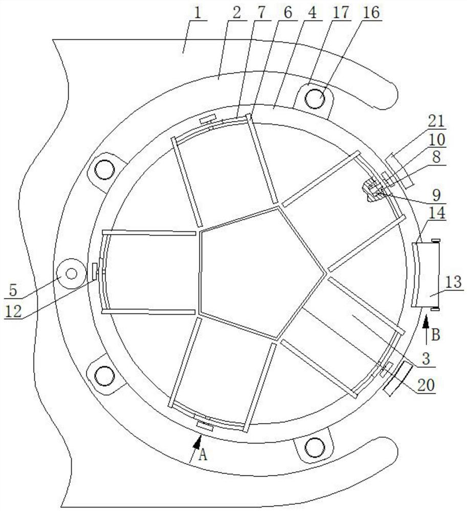
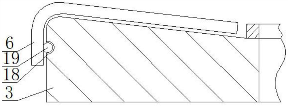
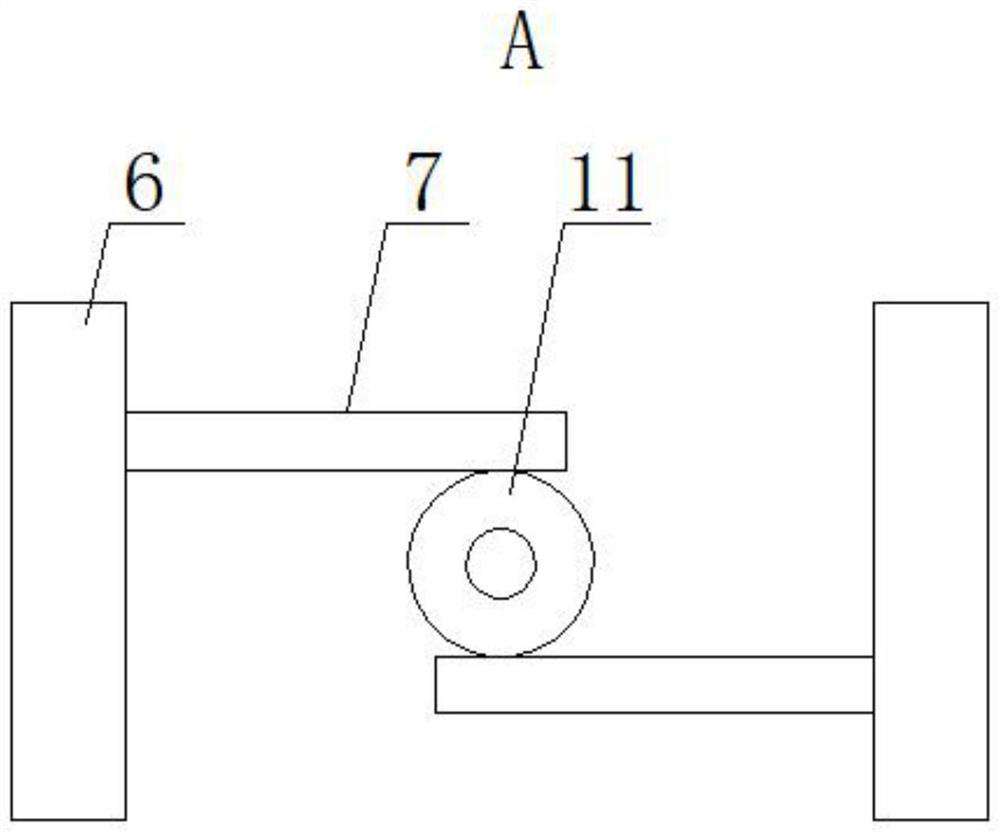
[0019] A laser cleaning device for tread blocks of tire molds, as shown in the figure, includes a platform 1, in actual use, the front of which is the working table, one side of the platform 1 is provided with a groove 2, and the front and outside of the groove 2 They are all connected to the outside world, the groove 2 is a C-shaped structure, an...


PUM


Abstract

The invention discloses a laser cleaning device for tire mold pattern blocks. The laser cleaning device comprises a platform, a groove is formed in one side of the platform, a mold supporting table is arranged in the groove, a translation mechanism connected with the mold supporting table is arranged in the groove, a gear ring is installed on the periphery of the mold supporting table, a gear column is arranged in the groove, the gear column is connected with a power device, a plurality of sets of clamping pieces are arranged on the mold supporting table, each set of clamping pieces comprise two clamping plates which are parallel to each other, a blind hole is formed in the side periphery of the mold supporting table, a one-way bearing is arranged in the blind hole, a rotating shaft is arranged in the one-way bearing, a second gear is arranged at the outer end of the rotating shaft, a support is arranged on the outer side of the groove, a wedge-shaped block is arranged in the support, a magnetic pole is arranged on the outer end face of the second gear, and electromagnets are arranged on the two sides of the support. According to the laser cleaning device, the height of the mold supporting table can be adjusted, so that the labor intensity of workers for taking and placing molds is relieved, meanwhile, the probability that the molds fall to be damaged or hurt the workers is reduced, automatic fixing and automatic unlocking can be achieved through cooperation of mechanical parts without manual operation of the workers, the device does not depend on a circuit structure and is prevented from being influenced by high temperature, and capital investment is lower.

Description

technical field [0001] The invention belongs to the field of laser cleaning, in particular to a laser cleaning device for pattern blocks of tire molds. Background technique [0002] Because laser cleaning can solve problems that cannot be solved by traditional cleaning methods such as chemical agents and mechanical methods, it has been widely used in various industries, such as mold cleaning. Laser cleaning technology refers to the use of high-energy laser beams to irradiate the surface of the workpiece, so that the dirt, rust spots or coatings on the surface evaporate or peel off instantly, and the attachments or surface coatings on the surface of the cleaning object can be removed at high speed and effectively, so as to achieve a clean process. What it cleans up is usually powder, so it needs supporting industrial vacuum equipment, such as a double-station laser cleaning equipment disclosed in the Chinese invention patent with the publication number CN210546793U, but in or...

Claims


Application Information

Patent Timeline
IPC IPC(8): B08B7/00B08B13/00B08B5/04B08B15/04
CPCB08B5/04B08B7/0042B08B13/00B08B15/04
Inventor 高峰任子涛林滋然
Owner WENZHOU POLYTECHNIC
Learn More