Pneumatic brake cylinder and brake clamp unit

A pneumatic brake and cylinder technology, applied in the field of rail transit, can solve problems such as alleviating gap instability, and achieve the effects of improving debugging efficiency, eliminating errors, and compact structure

Active Publication Date: 2021-06-01
CRRC QINGDAO SIFANG ROLLING STOCK RES INST +1
View PDF8 Cites 1 Cited by
  • Summary
  • Abstract
  • Description
  • Claims
  • Application Information

AI Technical Summary

Problems solved by technology

[0009] The present invention aims at the above-mentioned problems of the existing brake cylinder that the elastic deformation of the brake device cannot be identified during the braking process, resulting in the instability of the relief gap, etc., and provides a pneumatic brake cylinder and a brake caliper with an elastic recognition function The unit can complete the gap adjustment at one time, and the gap adjustment time is short, which improves the debugging efficiency of the whole vehicle and has high reliability

Method used


Image

  • Pneumatic brake cylinder and brake clamp unit
  • Pneumatic brake cylinder and brake clamp unit
  • Pneumatic brake cylinder and brake clamp unit

Examples


Embodiment 1

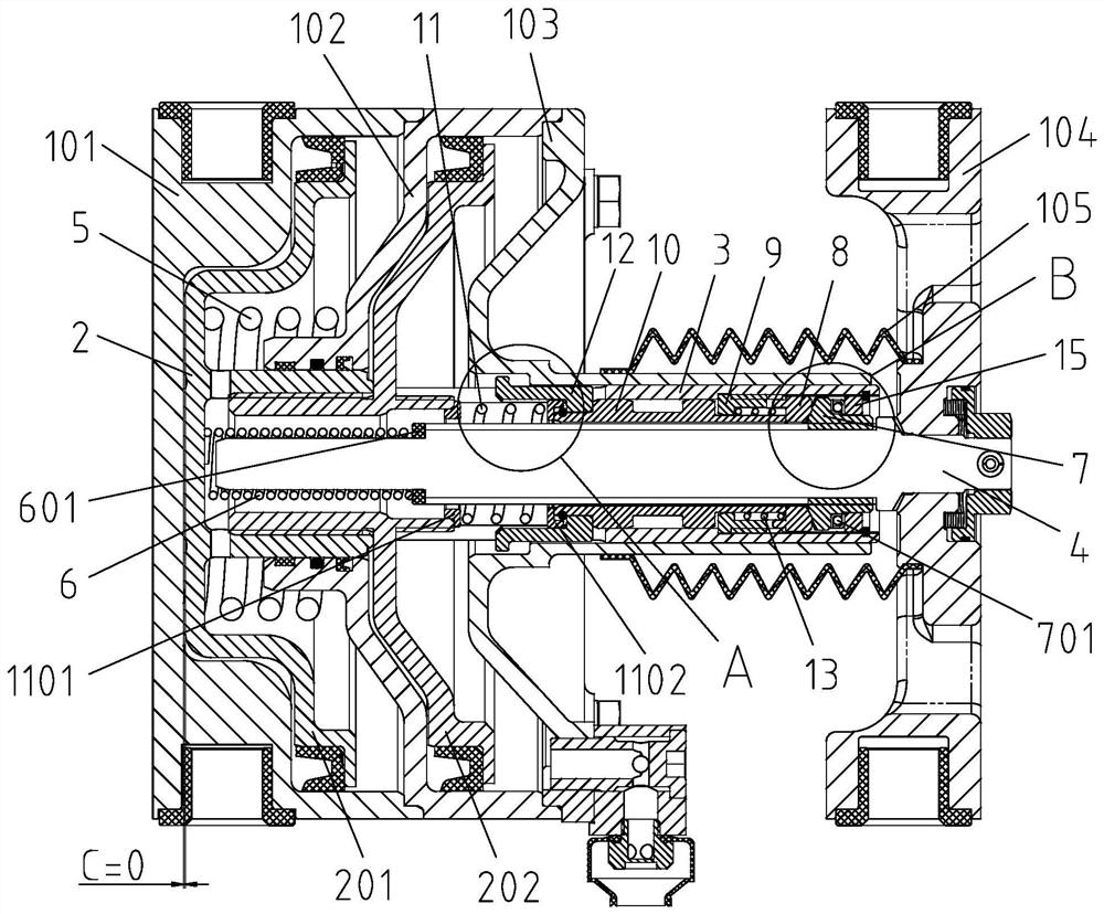
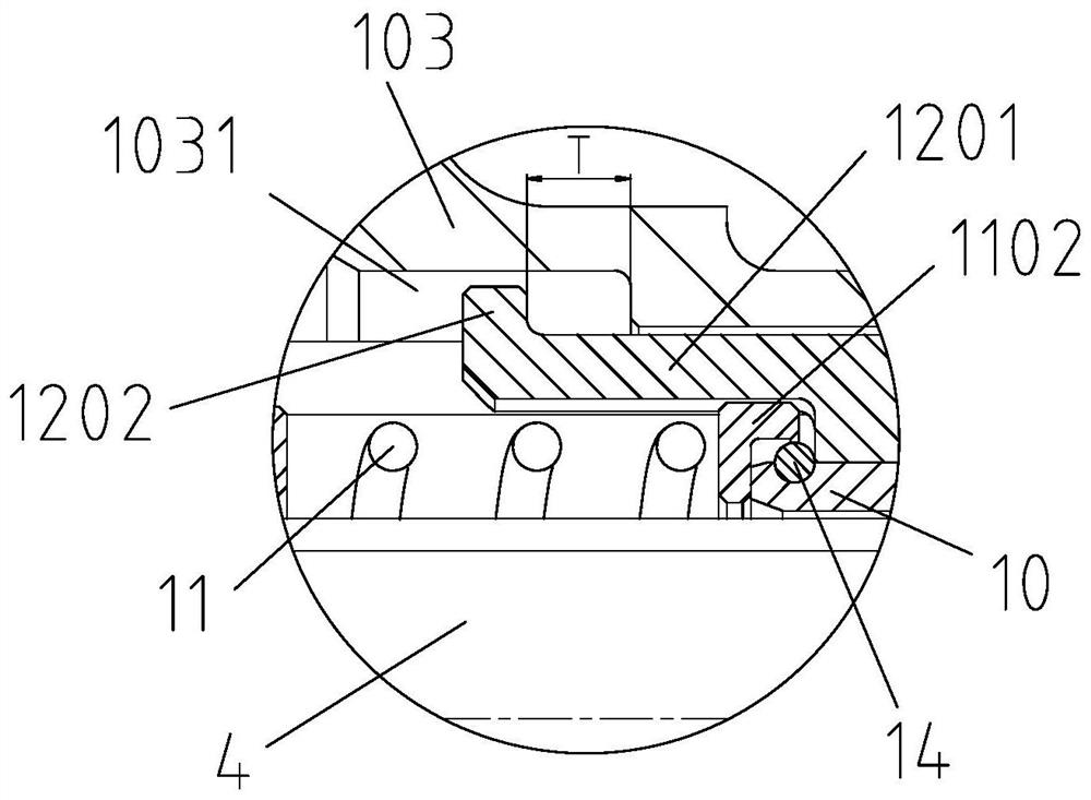
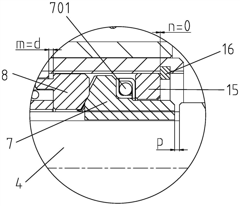
[0110] Example 1: Participation Figure 1 to Figure 3 , a pneumatic brake cylinder, including a cylinder body and a front end assembly 104, the cylinder body includes a rear cover assembly 101, an intermediate assembly 102 and a front cover assembly 103 connected in sequence, and the outside of the sleeve of the front cover assembly 103 is provided with A dustproof cover 105, one end of the dustproof cover 105 is connected to the front cover assembly 103, and one end is connected to the front end assembly 104; the cylinder body is provided with:

[0111] Piston assembly 2;

[0112] The piston sleeve 3 is connected with the piston assembly 2;

[0113] The lead screw 4 is arranged in the piston sleeve 3, and one end is connected with the front end assembly 104;

[0114] The relief spring 5 is arranged between the intermediate assembly 102 and the piston assembly 2;

[0115] Adjust the spring 6, one end is crimped to the piston assembly 2, and the other end is crimped to the l...

Embodiment 2

[0150] Example 2: see Figure 21 , a brake caliper unit, including a caliper assembly 17 and a pneumatic brake cylinder 18, the pneumatic brake cylinder 18 adopts the pneumatic brake cylinder described in Embodiment 1, and the pneumatic brake cylinder 18 is connected to the clip through a connecting bolt 20 The clamp arm 19 of the clamp assembly 17 is hinged.

[0151] In this embodiment, the brake caliper unit is installed on the bogie frame of the rail transit vehicle, and the brake disc is held tightly by the brake pad, and the kinetic energy of the train is converted into heat consumption by the friction between the brake pad holder and the brake disc. Dispersion, to achieve the effect of deceleration or parking.

Embodiment 3

[0152] Embodiment 3: see Figure 22 , a pneumatic brake cylinder, including a cylinder body and a front end assembly 104, the cylinder body includes a rear cover assembly 101, an intermediate assembly 102 and a front cover assembly 103 connected in sequence, and the outside of the sleeve of the front cover assembly 103 is provided with A dustproof cover 105, one end of the dustproof cover 105 is connected to the front cover assembly 103, and one end is connected to the front end assembly 104; the cylinder body is provided with:

[0153] Piston assembly 2;

[0154] The piston sleeve 3 is connected with the piston assembly 2;

[0155] The lead screw 4 is arranged in the piston sleeve 3, and one end is connected with the front end assembly 104;

[0156]The relief spring 5 is arranged between the intermediate assembly 102 and the piston assembly 2;

[0157] The adjustment spring 6 is arranged between the front cover assembly 103 and the front end assembly 104;

[0158] Gap adj...


PUM


Abstract

The invention relates to a pneumatic brake cylinder and a brake clamp unit. The pneumatic brake cylinder comprises a cylinder body and a front end assembly; the cylinder body is internally provided with a piston assembly; a piston sleeve is connected with the piston assembly; a lead screw is arranged in the piston sleeve, and one end of the lead screw is connected with the front-end assembly; a relieving spring is arranged between the cylinder body and the piston assembly; one end of an adjusting spring crimps the piston assembly, and the other end crimps the lead screw; an adjusting nut is arranged on the outer side of the lead screw; one side of the adjusting nut is provided with conical surface teeth; the other side of the adjusting nut is provided with a thrust bearing in contact with the piston sleeve; a conical tooth ring is sleeved on the lead screw and is matched with the conical surface teeth; a pushing ring is arranged on the piston sleeve; one end of the force transmission pipe is in contact with the bevel gear ring; the other end of the force transmission pipe is connected with the piston assembly through a gap identification spring sleeving the lead screw; a clearance identification ring is sleeved on the force transmission pipe and is in sliding connection with the piston sleeve; one end of the buffer spring is in compression joint with the bevel gear ring; and the other end of the buffer spring is in compression joint with the pushing ring. The pneumatic brake cylinder and a brake clamp unit are short in gap adjusting time and high in efficiency.

Description

technical field [0001] The invention belongs to the technical field of rail transit, and relates to rail vehicle braking technology, in particular to a pneumatic brake cylinder and a brake caliper unit. Background technique [0002] The brake cylinder is a key component of the braking system of rail transit vehicles, and has functions such as braking, relief, and clearance adjustment. [0003] The existing brake cylinder has the following disadvantages: [0004] (1) The structure is complex, the number of parts is large, and the reliability is poor. When assembling, the gap needs to be adjusted manually, the assembly efficiency is low, and the manual adjustment can easily lead to errors. [0005] (2) There is a chute or boss on the outside of the brake cylinder to adjust and relieve the gap. In the case of accidental damage to the dust cover, the dirt and sand will easily enter the inside of the brake cylinder and damage the parts inside the brake cylinder. [0006] (3) Mo...

Claims


Application Information

Patent Timeline
Patent Type & Authority Applications(China)
IPC IPC(8): F16D65/18F16D65/56F16D121/04F16D125/02
CPCF16D65/18F16D65/567F16D2121/04F16D2125/02
Inventor 孟庆余覃立伟张昕王风洲徐少亭刁有彬
Owner CRRC QINGDAO SIFANG ROLLING STOCK RES INST
Why Eureka
Try Eureka