Flue purification device modular layout method

A technology of purification device and layout method, which is applied in the direction of combustion method, exhaust gas device, combustion product treatment, etc., to achieve the effects of reducing eddy current, good sealing effect, and easy disassembly and maintenance.

Pending Publication Date: 2021-06-01
HUADIAN ELECTRIC POWER SCI INST CO LTD +1
View PDF4 Cites 0 Cited by
  • Summary
  • Abstract
  • Description
  • Claims
  • Application Information

AI Technical Summary

Problems solved by technology

All these technologies put forward higher requirements for the arrangement of the flue cleaning device. It is a challenge for a large flue to arrange a

Method used


Image

  • Flue purification device modular layout method
  • Flue purification device modular layout method
  • Flue purification device modular layout method

Examples


Example Embodiment

[0023]Example 1.

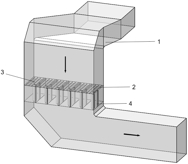
[0024]Seefigure 1 ,2, 5, the present embodiment provides a modular layout method for the flue purification apparatus, arranged in the tail flue 1, and the tail flue 1 includes vertical flue and horizontal flue, select 1 tail flue 1 The vertical flue portion is arranged in the casing module 3, avoiding the elbow, at the size of the head, and the shaped pipe.

[0025]The size of the casing module 3 is designed according to the load, according to the size and flue gas amount of the flue, calculates the number of boxes, using 6 case modules 3, and 6 case modules 3 are arranged in the same plane. And the six case modules 3 are connected to a semi-circular sealing connection method A, and the flow field of the inlet is ensured, and the anti-corrosion is sealed.

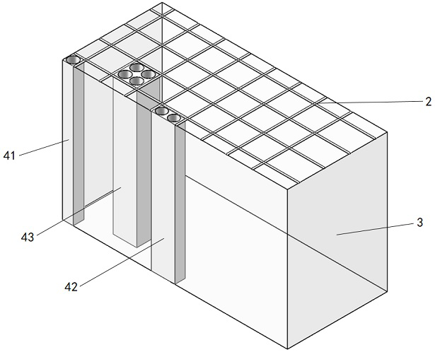
[0026]A support module 2 is provided in the box module 3, and the support module 2 is divided into different regions, and the support module 2 includes an outer support structure and an inner support structure, and the ...

Example Embodiment

[0029]Example 2.

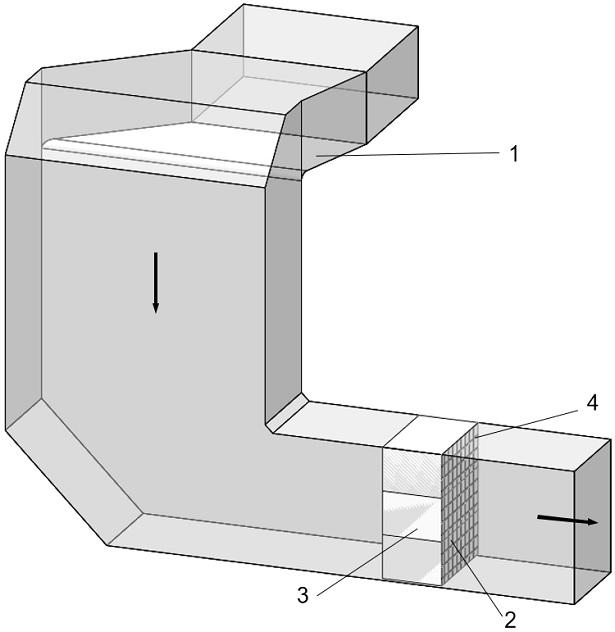
[0030]Seeimage 3 ,4, 5, the present embodiment provides a modular layout method for the flue purification apparatus, arranged in the tail flue 1, and the tail flue 1 includes vertical flue and horizontal flue, select 1 tail flue 1 Horizontal flue partial arrangement of the box module 3, avoid the elbow, the size of the head, and the shaped pipe.

[0031]The size of the box module 3 is designed according to the load, according to the size and flue gas amount of the flue, calculates the number of boxes, using 3 case modules 3, and 3 case modules 3 are arranged in the same plane. And the three case modules 3 use a inferior arc-shaped sealing connection method C to ensure the flow field of the inlet, while sealing the anti-corrosion.

[0032]A support module 2 is provided in the box module 3, and the support module 2 is divided into different regions, and the support module 2 includes an outer support structure and an inner support structure, and the outer support structure is...


PUM


Abstract

The invention discloses a flue purification device modular layout method, and belongs to the field of energy conservation and environmental protection. Box body modules are arranged in a tail flue, the tail flue comprises a vertical flue and a horizontal flue, the horizontal flue part or the vertical flue part is selected at the tail flue to arrange the box body module, and elbows, reducers and special-shaped pipelines are avoided. The size of the box body modules is designed according to bearing, and meanwhile the smoke amount is considered. Considering the expansion of a box body, the flow field at an inlet is not influenced, and the box body modules can be connected in an arc-shaped, inferior arc-shaped, triangular and other modes. A supporting module is arranged in each box body module, a purification module is placed in each supporting module, the purification modules adopt a cylindrical tube bundle type structure, one, two or four cylindrical tube bundle type structures form a purification unit, and each purification unit can be relatively independently disassembled or assembled in the corresponding supporting module. Uniform flowing of airflow in a flue is facilitated, and generation of vortexes is reduced.

Description

Technical field[0001]The present invention relates to a large-scale flue purification device of coal-fired power plants, belonging to the field of energy saving and environmental protection, especially suitable for large three-dimensional complex flow of electricity, petrochemical, metallurgy, and construction. Layout flue purification device layout.Background technique[0002]The strength of pollutants in coal-fired power plants is large, and the technological desulfurization and dust removal facility has been behind, it has become one of the important factors that cause atmospheric pollution. Wet desulfurization techniques such as traditional bicycracy, ammonia, limestone plaster method are large, easy to cause pipeline corrosion or blockage, complex operation, investment and operational maintenance cost, and severe secondary pollution. At present, the technology of the internal arrangement of purification devices in the tail flue provides a good way to power plant pollutant emissio...

Claims


Application Information

Patent Timeline
IPC IPC(8): F23J11/12F23J13/04F23J15/02
CPCF23J11/12F23J13/04F23J15/006F23J15/02
Inventor 董方王勇陈军马治安彭丽李宗慧柳冠青石战胜
Owner HUADIAN ELECTRIC POWER SCI INST CO LTD
Why Eureka
Try Eureka