
Method for monitoring ground subsidence of mining subsidence area based on three-dimensional laser scanning

A technology of three-dimensional laser and subsidence area, which is applied in the directions of measuring devices, surveying and navigation, height/horizontal measurement, etc. It can solve the problems of increased transmission error, complicated operation, unstable tripod, etc., and achieves increased leveling range and accuracy and high stability

Active Publication Date: 2021-06-01
INST OF ROCK AND SOIL MECHANICS - CHINESE ACAD OF SCI
View PDF4 Cites 1 Cited by
  • Summary
  • Abstract
  • Description
  • Claims
  • Application Information

AI Technical Summary

Problems solved by technology

[0004] (1) Due to the severe deformation of the ground surface near the mining subsidence area, the surface rock and soil in these areas are relatively broken and soft, which leads to the instability of the tripod erected on the surface near the mining subsidence area. The rounded triangular plate is in a horizontal state, and when a relatively bulky 3D laser scanner is mounted on a tripod, due to the heavy weight of the 3D laser scanner, the lower end of the tripod is often inserted into the unstable surface rock. Due to the movement of the soil, the rounded triangular plate of the tripod tilts and is not in a horizontal state, and sometimes it may even cause the rounded triangular plate to change from a horizontal state at the beginning of the measurement to an unlevel state during the measurement process, resulting in measurement results The significant error cannot be applied to engineering practice
Although it is possible to set up a tripod in a relatively stable area slightly away from the mining subsidence area, it is often difficult to directly view the deep subsidence site due to obstructions and the limited height of the 3D laser scanner. Obtain all the point cloud data of the surface of the mining subsidence area, especially the point cloud data of the bottom of the collapse pit
Therefore, the existing method of using a tripod to set up a 3D laser scanner is difficult to monitor the ground subsidence in the mining subsidence area.
[0005] (2) When the 3D laser scanner is used on the existing tripod to obtain the surface point cloud data of the mining subsidence area and the commonly used contact measurement method GPS locator is used to obtain the 3D coordinates of the reference station, it is necessary to manually use a tape measure to measure the data from the 3D The laser scanner scans the distance between the height mark of the altitude and the height mark of the antenna of the GPS locator to the centering observation point of the tripod on the ground. This is often because when the man-made height is high, the two ends of the tape measure are in alignment with the height mark and the ground. There is a significant error when centering the observation point, and sometimes the error can reach about 10 mm. Such an error is not allowed for the monitoring of surface deformation in mining areas. For example, the allowable value of the station error when the level is used to measure the surface settlement Requires no more than 1 mm
Therefore, due to the artificial measurement of the scanning height of the 3D laser scanner and the antenna height of the GPS locator, the error caused sometimes does not meet the engineering measurement requirements
In addition, the traditional method of using a tripod to set up a 3D laser scanner and a GPS locator requires adjusting the tripod to center the observation point on the ground during measurement. The entire measurement process takes a long time and is complicated to operate.
[0006] (3) The existing main method of splicing the point cloud data obtained by scanning the three-dimensional laser stations at each station is based on the common feature points or public target spheres between the two stations. Accumulation of cloud data errors, resulting in transfer errors that increase with the number of stations, greatly reducing the accuracy of scanned data

Method used


Image

  • Method for monitoring ground subsidence of mining subsidence area based on three-dimensional laser scanning
  • Method for monitoring ground subsidence of mining subsidence area based on three-dimensional laser scanning
  • Method for monitoring ground subsidence of mining subsidence area based on three-dimensional laser scanning

Examples


Embodiment 1

[0065] Below in conjunction with accompanying drawing, the present invention is described in further detail:

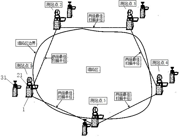
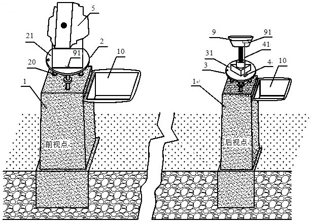
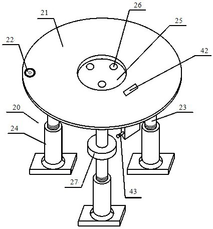
[0066] according to Figure 1~Figure 13 As shown, a method for monitoring ground subsidence in mining subsidence areas based on 3D laser scanning,

[0067] Step S01. According to the scope of the mining subsidence area and the optimal scanning radius of the three-dimensional laser scanner 5, a plurality of stations are arranged on the surface around the periphery of the mining subsidence area, such as figure 1 Shown; The distance between two adjacent stations around the mining subsidence area is twice the optimal scanning radius of the three-dimensional laser scanner 5, and the distance between the center of the mining subsidence area and each station station is no more than twice the three-dimensional laser scanning The scanning radius of instrument 5, makes the area of ​​all circles drawn with each station point as the center position cover the mining subsidence ar...


PUM


Abstract

The invention discloses a method for monitoring ground subsidence of a mining subsidence area based on three-dimensional laser scanning. The method comprises the following steps: arranging a plurality of observation stations on the ground surface around the periphery of the mining subsidence area according to the range of the mining subsidence area and the optimal scanning radius of a three-dimensional laser scanner; correspondingly arranging a positioning point beside each station; embedding two concrete monitoring piers in the station site and the positioning point respectively, and mounting a front-view base disc and a rear-view base disc which can be leveled; placing a three-dimensional laser scanner on the front-view base disc, and carrying out point cloud data acquisition; placing a GPS position indicator on the front-view base disc and the rear-view base disc to measure the three-dimensional coordinates of the station point and the positioning point; and performing splicing, filtering, denoising and other processing on the point cloud data obtained by each station according to the absolute three-dimensional coordinates under the coordinate system of the mining subsidence area to obtain the ground scanning terrain of the whole mining subsidence area, thereby obtaining the single settlement deformation and multi-period accumulated settlement deformation values of the ground surface of the mining subsidence area. By adopting the method, the convenience, the accuracy and the efficiency of monitoring the ground subsidence of the mining subsidence area are greatly improved, the change of the ground subsidence of the mining subsidence area can be known in time, and technical support is provided for ensuring safe operation of a mine and guiding underground safe production.

Description

technical field [0001] The invention belongs to the technical field of geotechnical engineering ground surface deformation measurement, and more specifically relates to a method for monitoring ground subsidence in mining subsidence areas based on three-dimensional laser scanning, which is suitable for long-term monitoring of ground subsidence in mining subsidence areas. Background technique [0002] At present, various environmental problems caused by the development of underground mineral resources come one after another, among which the surface movement and subsidence of the mining area are particularly prominent, and the subsidence amount can reach 1m per month. Especially in underground metal mines mined by caving method, large-scale subsidence, cracking and settlement are often formed on the surface, which has become a major safety and geological environmental problem in underground mining of metal mines. In order to be able to understand and predict the distribution an...

Claims


Application Information

Patent Timeline
IPC IPC(8): G01C5/00
CPCG01C5/00
Inventor 夏开宗陈从新张褚强王月王田龙刘轩廷
Owner INST OF ROCK AND SOIL MECHANICS - CHINESE ACAD OF SCI
Learn More