Supercharge Your Innovation With Domain-Expert AI Agents!

Schottky rectifier tube manufacturing method and Schottky rectifier tube

A technology of rectifier tubes and encapsulation shells, which is applied in the field of manufacturing Schottky rectifier tubes, can solve the problems of low processing efficiency and cumbersome procedures, and achieve the effects of high manufacturing efficiency, short time and simple structure

Active Publication Date: 2021-06-01
互创(东莞)电子科技有限公司
View PDF6 Cites 0 Cited by
  • Summary
  • Abstract
  • Description
  • Claims
  • Application Information

AI Technical Summary

Problems solved by technology

Using the above conventional processing procedures to produce Schottky rectifier tubes, the procedures are cumbersome and the processing efficiency is low

Method used


Image

  • Schottky rectifier tube manufacturing method and Schottky rectifier tube
  • Schottky rectifier tube manufacturing method and Schottky rectifier tube
  • Schottky rectifier tube manufacturing method and Schottky rectifier tube

Examples


Embodiment Construction

[0026] The present invention will be further described in detail below with reference to the examples and drawings, but the implementation of the present invention is not limited thereto.

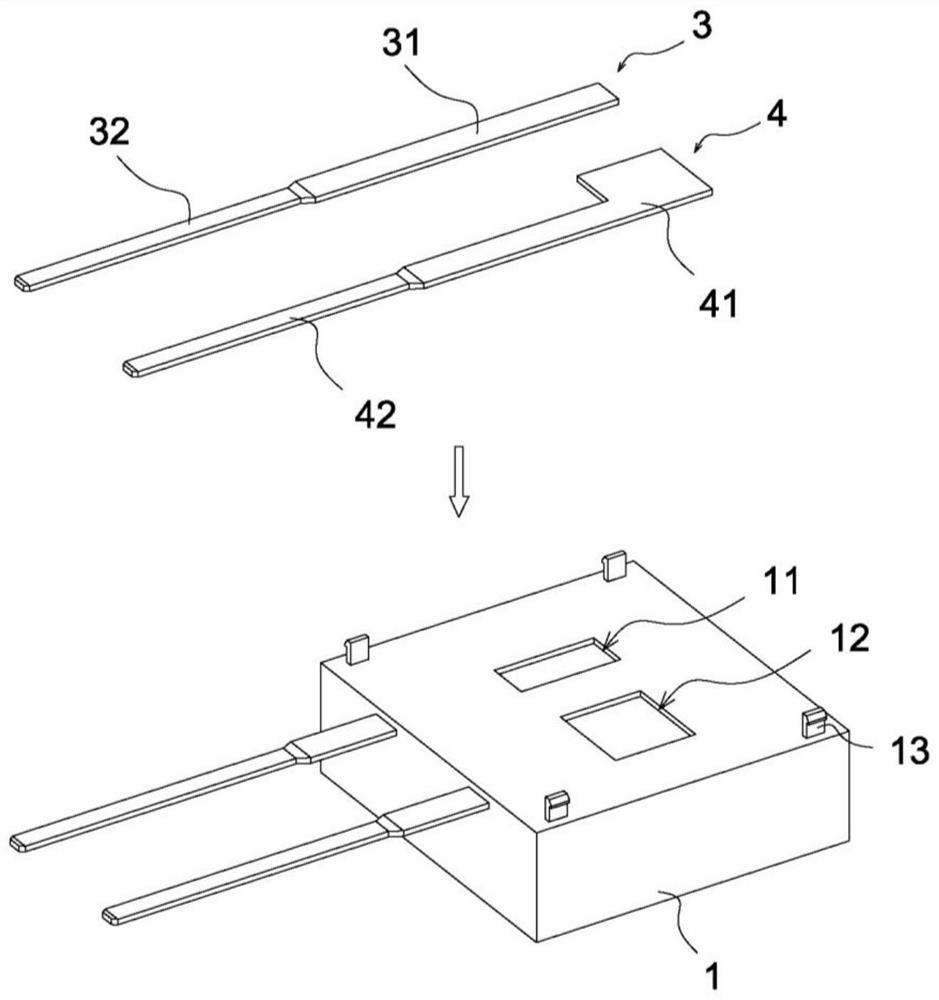
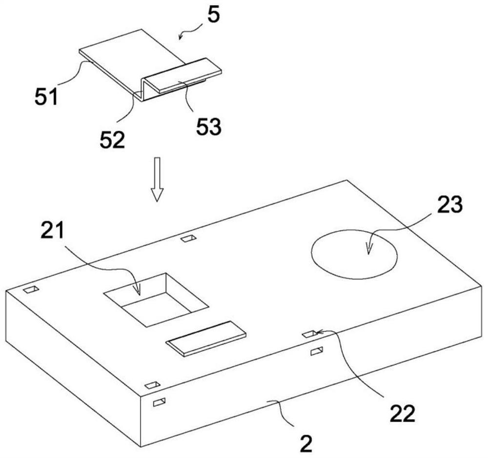
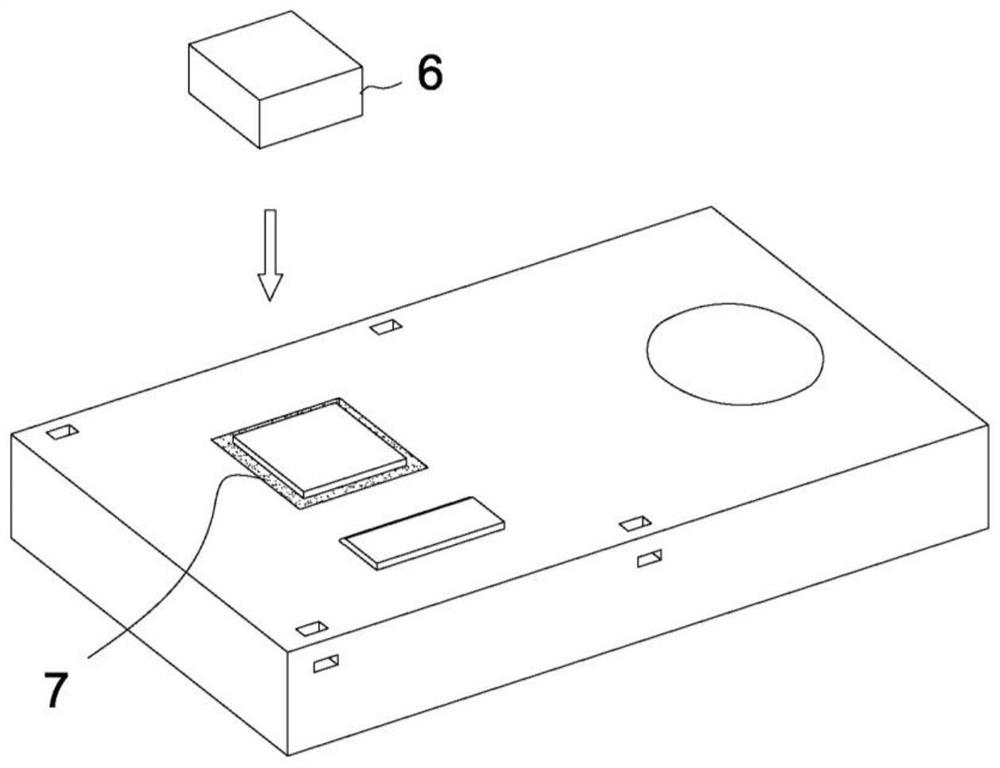
[0027] Such as Figure 1-4 Shown:

[0028] A Schottky rectifier, comprising a first package 1, a second package 2, a first terminal 3, a second terminal 4, a third terminal 5, a Schottky chip 6, the first package 1 and the second The package shell 2 is buckled and connected, the first terminal 3 and the second terminal 4 are integrally formed with the first package shell 1 , the third terminal 5 is integrally formed with the second package shell 2 ; the first terminal 3 includes a first contact portion 31 , the first extension part 32, the first hollow groove 11 is formed on the first package shell 1, the first hollow groove 11 is located on the upper side of the first contact part 31, and the first extension part 32 is located outside the first package shell 1; The terminal 4 includes a ...


PUM


Abstract

The invention provides a Schottky rectifier tube manufacturing method and a Schottky rectifier tube, the Schottky rectifier tube comprises a first packaging shell, a second packaging shell, a first terminal, a second terminal, a third terminal and a Schottky chip, the first packaging shell is connected with the second packaging shell in a buckling mode, the first terminal, the second terminal and the first packaging shell are integrally formed, and the Schottky chip is arranged in the first packaging shell. And the third terminal and the second packaging shell are integrally formed. According to the Schottky rectifier tube manufacturing method and the Schottky rectifier tube, the Schottky rectifier tube can be manufactured through the procedures of punching forming, injection molding, chip fixing and buckling forming, the structure is simple, the number of steps is small, and the manufacturing efficiency is high.

Description

technical field [0001] The invention relates to the technical field of Schottky rectifiers, in particular to a method for manufacturing a Schottky rectifier and the Schottky rectifier. Background technique [0002] Schottky rectifier is a metal-semiconductor device made of noble metal (gold, silver, aluminum, platinum, etc.) A as the positive electrode and N-type semiconductor B as the negative electrode. . Because there are a large number of electrons in the N-type semiconductor and only a small amount of free electrons in the noble metal, the electrons diffuse from B with high concentration to A with low concentration. Obviously, there are no holes in metal A, and there is no diffusion of holes from A to B. As electrons continue to diffuse from B to A, the electron concentration on the surface of B gradually decreases, and the surface electrical neutrality is destroyed, thus forming a potential barrier, and its electric field direction is B→A. However, under the action ...

Claims


Application Information

Patent Timeline
Patent Type & Authority Applications(China)
IPC IPC(8): H01L23/04H01L23/10H01L29/872
CPCH01L23/04H01L23/10H01L29/872
Inventor 张锦鹏
Owner 互创(东莞)电子科技有限公司
Features
  • R&D
  • Intellectual Property
  • Life Sciences
  • Materials
  • Tech Scout
  • Unparalleled Data Quality
  • Higher Quality Content
  • 60% Fewer Hallucinations
Learn More