LED driving circuit and driving controller and control method thereof

A technology of LED drive and controller, applied in the control of LED drive circuit, in the field of LED drive circuit, can solve the problems of continuous inductive current, damage of power tube M0, high cost, etc., to prevent misjudgment of inductive current zero crossing, reduce volume and cost, avoiding the effect of continuous inductor current

Active Publication Date: 2021-06-01
HANGZHOU SILAN MICROELECTRONICS
View PDF9 Cites 2 Cited by
  • Summary
  • Abstract
  • Description
  • Claims
  • Application Information

AI Technical Summary

Problems solved by technology

If the input capacitor Cin after the rectifier bridge is removed, the power noise and fluctuation of the AC input signal AC_IN will be loaded on the power supply terminal HV of the drive controller 100 and the drain of the power transistor M0 through the input voltage VIN, which may easily cause false detection by the drive controller zero-crossing to allow the inductor current to continue, image 3 It shows the schematic diagram of the waveform change of the inductor current IL in the normal critical conduction mode and the inductor current IL after the input capacitor Cin is removed
It can be seen that removing the input capacitor Cin will destroy the constant current characteristics of the LED drive circuit, causing the LED lights to flicker, and easily damage the power tube M0 due to overcurrent.
[0008] The input capacitor Cin directly filters the input voltage VIN after the rectifier bridge BD0, which requires high withstand voltage and high capacity, so for the entire LED drive circuit, it is not only bulky but also expensive

Method used


Image

  • LED driving circuit and driving controller and control method thereof
  • LED driving circuit and driving controller and control method thereof
  • LED driving circuit and driving controller and control method thereof

Examples


Embodiment Construction

[0086] Various embodiments of the invention will be described in more detail below with reference to the accompanying drawings. In the various drawings, the same elements are denoted by the same or similar reference numerals. For the sake of clarity, various parts in the drawings have not been drawn to scale.

[0087] Unless otherwise specified, the "off time", "on time" and "switching period" in the present disclosure all represent corresponding stages and corresponding time lengths.

[0088] The invention can be embodied in various forms, some examples of which are described below.

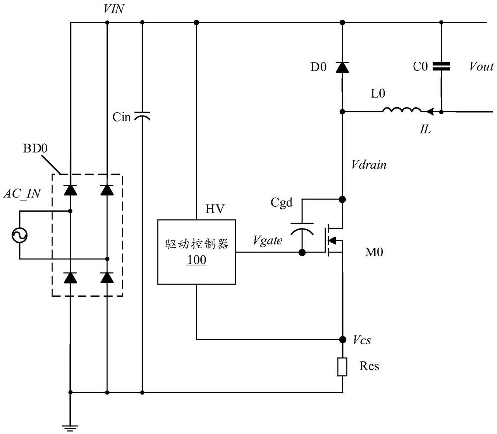
[0089] The present invention provides an LED drive circuit and its drive controller that do not need to connect a filter capacitor at the output end of the rectifier bridge. The LED drive circuit and drive controller can be coupled with an inductor to detect the inductor current to generate a Zero detection signal, and provide prediction enabling signal, so that the pulse that zero-crossing de...


PUM


Abstract

The invention discloses an LED driving circuit and a driving controller and a control method thereof. The LED driving controller comprises a zero-crossing indication circuit which carries out inductive current zero-crossing detection and provides a zero-crossing indication signal, a peak value comparison circuit that is used for generating a peak value indication signal according to a comparison result of the sampling voltage representing the current flowing through the power tube and the first reference voltage, and a driving control circuit which is used for controlling the on and off of the power tube according to the zero-crossing indication signal and the peak indication signal; the zero-crossing indication circuit is used for detecting the inductive current to generate a zero-crossing detection signal and providing a prediction enable signal; and a pulse provided by the zero-crossing detection signal under the condition that the enable signal is predicted to be in the first state as an interference pulse is filtered so as to generate a zero-crossing indication signal. According to the LED driving circuit and the driving controller and the control method thereof, a filter capacitor at the output end of a rectifier bridge can be omitted, interference pulses in zero-cross detection signals can be eliminated, and the problem that inductive current is continuous in a critical conduction mode is solved.

Description

technical field [0001] This article relates to switching power supply technology, especially to LED drive circuits, LED drive controllers and control methods for LED drive circuits. Background technique [0002] In switching power supply systems, capacitors are generally indispensable as filter devices after the rectifier bridge. [0003] figure 1 A schematic structural diagram of a traditional LED driving circuit is shown. Such as figure 1 As shown, the LED drive circuit is a non-isolated step-down structure, including: rectifier bridge BD0, input capacitor Cin, power tube M0, drive controller 100, inductor L0, sampling resistor Rcs, output capacitor C0 and freewheeling diode D0. [0004] Wherein, the rectifier bridge BD0 receives the AC input signal AC_IN and rectifies the AC input signal AC_IN, the positive output terminal of the rectifier bridge BD0 is connected to the first terminal of the input capacitor Cin to provide the input voltage VIN, and the negative output...

Claims


Application Information

Patent Timeline
Patent Type & Authority Applications(China)
IPC IPC(8): H05B45/30H05B45/37H05B45/345
CPCH05B45/30H05B45/37H05B45/345Y02B20/30Y02B20/40
Inventor 朱晓杰姚云龙
Owner HANGZHOU SILAN MICROELECTRONICS
Why Eureka
Try Eureka