Rotary silicon target material capable of being uniformly sputtered and preparation method of rotary silicon target material

A silicon target and sputtering technology, which is applied in the field of uniform sputtering rotating silicon target and its preparation, can solve the problems of reducing the utilization rate and service life of the target, grooves at both ends of the target, and high sputtering rate

Pending Publication Date: 2021-06-04
FUJIAN ACETRON NEW MATERIALS CO LTD
View PDF10 Cites 0 Cited by
  • Summary
  • Abstract
  • Description
  • Claims
  • Application Information

AI Technical Summary

Problems solved by technology

During the silicon target magnetron sputtering process, since the liner is equipped with a magnetic rod and the magnetic poles are close to both ends of the liner, the magnetic field at both ends of the silicon target will be relatively strong, resulting in a significantly higher sputtering rate at both ends than in the middle. The "groove" phenomenon appears at both ends of the target material, which seriously reduces the utilization rate and service life of the target material

Method used


Image

  • Rotary silicon target material capable of being uniformly sputtered and preparation method of rotary silicon target material
  • Rotary silicon target material capable of being uniformly sputtered and preparation method of rotary silicon target material
  • Rotary silicon target material capable of being uniformly sputtered and preparation method of rotary silicon target material

Examples


preparation example Construction

[0035] The present invention provides a method for preparing the above-mentioned rotating silicon target that can be evenly sputtered, comprising the following steps:

[0036] (1) Under a protective atmosphere, arc spray self-adhesive layer material to the surface of the liner to obtain a liner with a self-adhesive layer;

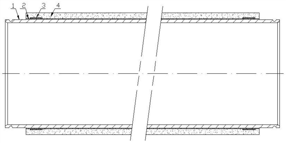
[0037] (2) Under a protective atmosphere, plasma thermal spraying magnetic material powder is applied to both ends of the self-adhesive layer surface in the liner with the self-adhesive layer to form a first magnetic material layer and a second magnetic material layer to obtain a magnetic material having The liner of the material layer;

[0038] (3) Under a protective atmosphere, plasma thermal spraying silicon powder on the outer surface of the liner with the magnetic material layer to form an outer layer of silicon to obtain a rotating silicon target that can be evenly sputtered.

[0039] In the invention, the self-adhesive layer material is arc-sprayed ...

Embodiment 1

[0057] Preparation specification is OD 2 149 / OD 1 133-ID125*L940 rotating silicon target, target thickness = (OD 2 -OD 1 ) / 2=8mm(where OD 2 is the outer diameter of the silicon target, OD 1 is the outer diameter of the liner, ID is the inner diameter of the liner, and L is the length of the silicon target).

[0058] The preparation method is as follows:

[0059] (1) The liner is machined according to the required size, and cleaned and sandblasted. Ultrasonic cleaning is used for cleaning, and 12# white corundum is used for sandblasting to roughen the surface, with a surface roughness of 89 μm.

[0060] (2) Place the liner in a nitrogen atmosphere protection chamber, use φ2.4mm aluminum-clad nickel composite wire (aluminum accounts for 5wt%), and use atmosphere-protected arc spraying equipment for spraying, and the thickness of the self-adhesive layer is 0.3mm; spraying The main process gas is nitrogen, the nitrogen pressure is 0.6MPa, the voltage is 43V, and the current ...

Embodiment 2

[0070] Preparation specification is OD 2 145 / OD 1 133-ID125*L850 rotating silicon target, target thickness = (OD 2 -OD 1 ) / 2=6mm(where OD 2 is the outer diameter of the silicon target, OD 1 is the outer diameter of the liner, ID is the inner diameter of the liner, and L is the length of the silicon target).

[0071] The preparation method is as follows:

[0072] (1) The liner is machined according to the required size, and cleaned and sandblasted. Ultrasonic cleaning is used for cleaning, and 12# white corundum is used for sandblasting to roughen the surface, and the surface roughness is 118μm.

[0073] (2) Place the liner in a nitrogen atmosphere protection chamber, use φ2mm aluminum-clad nickel composite wire (aluminum accounts for 3wt%), and use atmosphere-protected arc spraying equipment for spraying, and the thickness of the self-adhesive layer is 0.3mm; the main process of spraying The gas is nitrogen, the nitrogen pressure is 0.8MPa, the voltage is 45V, and the cu...


PUM

PropertyMeasurementUnit
thicknessaaaaaaaaaa
lengthaaaaaaaaaa
thicknessaaaaaaaaaa

Abstract

The invention provides a rotary silicon target material capable of being uniformly sputtered and a preparation method thereof, and belongs to the technical field of silicon target materials. The rotating silicon target capable of being uniformly sputtered comprises a liner tube, a self-bonding layer located on the outer surface of the liner tube, a first magnetic material layer, a second magnetic material layer and a silicon outer layer from inside to outside, wherein the first magnetic material layer and the second magnetic material layer are located at the two ends of the surface of the self-bonding layer; and the first magnetic material layer is close to a first port of the self-bonding layer and is 3-5 mm away from the outer edge of the first port of the self-bonding layer, and the second magnetic material layer is close to a second port of the self-bonding layer and is 3-5 mm away from the outer edge of the second port of the self-bonding layer. The magnetic material layers are arranged at the two ends of the surface of the self-bonding layer, so that magnetic fields generated at the two ends of a magnetic rod in the magnetron sputtering process can be counteracted, the sputtering rate of the two ends is reduced, and the use degrees of the two ends of the silicon target are kept consistent with the use degree of the middle.

Description

technical field [0001] The invention relates to the technical field of silicon targets, in particular to a rotating silicon target capable of uniform sputtering and a preparation method thereof. Background technique [0002] In recent years, with the rapid development of new devices and new materials in the global microelectronics industry, electronic, magnetic, optical and superconducting thin films are widely used in high-tech and industrial fields, and higher requirements are put forward for high-quality targets, large-scale and utilization high demands. High-purity silicon target is an important high-end target, mainly used in mobile phone screens, solar panels, tablet computer screens, integrated circuits, etc., and is an indispensable key foundation for important industries such as electronic information industry and new energy industry. Material. [0003] Magnetron sputtering is a physical deposition method. Its principle is that under the interaction of magnetic fi...

Claims


Application Information

Patent Timeline
Patent Type & Authority Applications(China)
IPC IPC(8): C23C14/35C23C4/131C23C4/04
CPCC23C14/35C23C14/3407C23C4/131C23C4/04
Inventor 林志河
Owner FUJIAN ACETRON NEW MATERIALS CO LTD
Why Eureka
Try Eureka