
Staged invisible closed automatic road drainer

A staged, drainer technology, applied in drainage structures, waterway systems, water supply devices, etc., can solve problems such as poor drainage, affecting vision, and small drainage area, and achieve the effect of facilitating drainage.

Active Publication Date: 2021-06-04
SHANXI TRAFFIC PLANNING PROSPECTING & DESIGN INST
View PDF10 Cites 0 Cited by
  • Summary
  • Abstract
  • Description
  • Claims
  • Application Information

AI Technical Summary

Problems solved by technology

However, there are many problems in the current highway drainage system. The first is the lack of drainage capacity. The area available for drainage per unit area is small. Due to the beautiful design of the road surface, there will not be too many rainwater wells, which limits drainage. When the amount of rain is heavy, there will be a lot of water on the road surface. When a car passing at high speed, the rain will splash, affect the vision, pollute the vehicle, easily cause traffic accidents, and threaten traffic safety. At the same time, the water will also be serious. damage to the pavement structure, causing serious consequences such as cracks and subsidence
[0003] In the existing highway drainage system, the water inlet is often equipped with a grate. When there is no daily rain, it is in an open state. The sediment or sundries are transported into the drainage pipe by the wind or artificially. The existing urban drainage pipes are basically half blocked. Or the state of complete blockage leads to poor drainage. At the same time, the open state of the rainwater well provides living space for insects and mice, becoming a dead corner of the city, and there will be a certain amount of peculiar smell.

Method used


Image

  • Staged invisible closed automatic road drainer
  • Staged invisible closed automatic road drainer
  • Staged invisible closed automatic road drainer

Examples


Embodiment

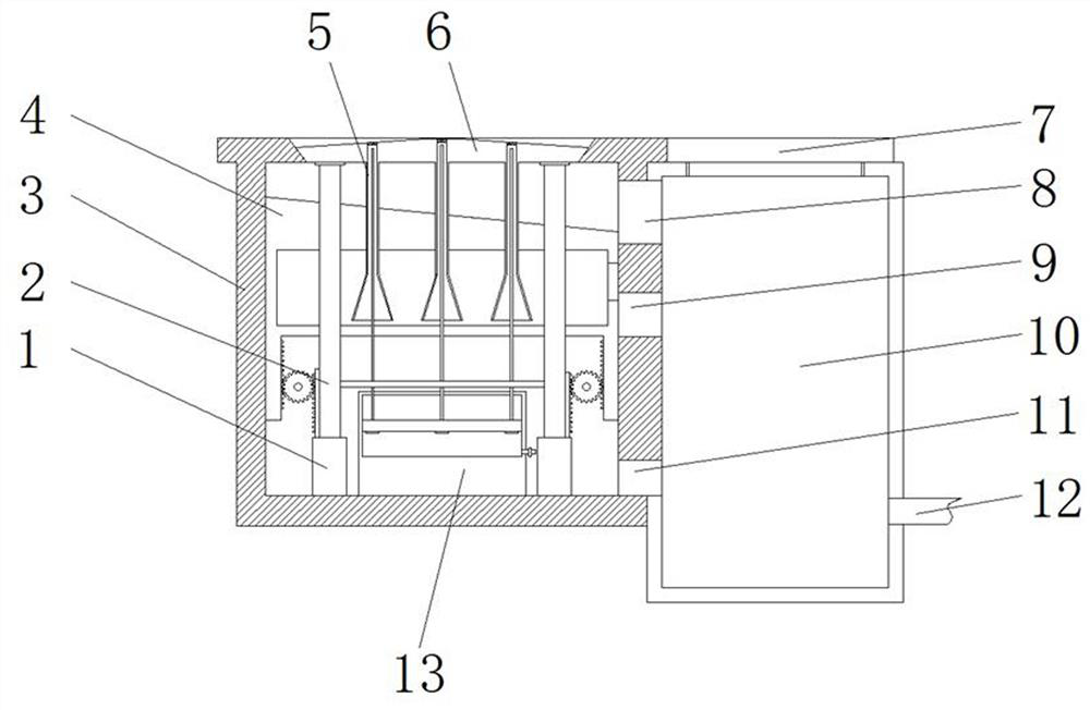
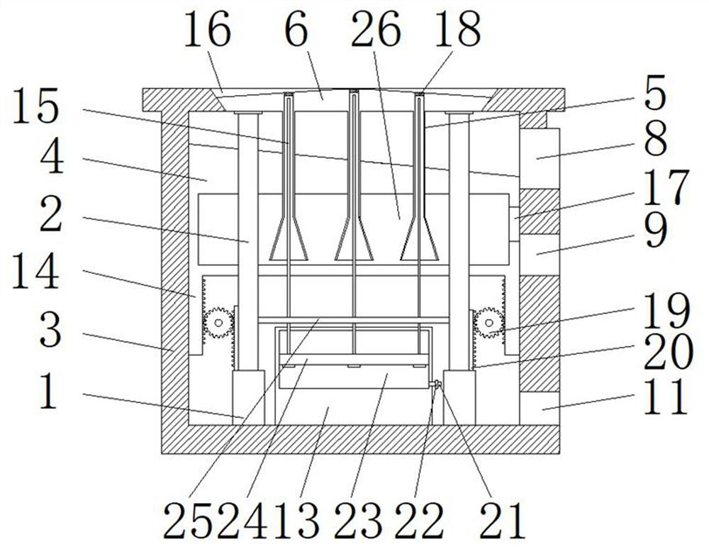
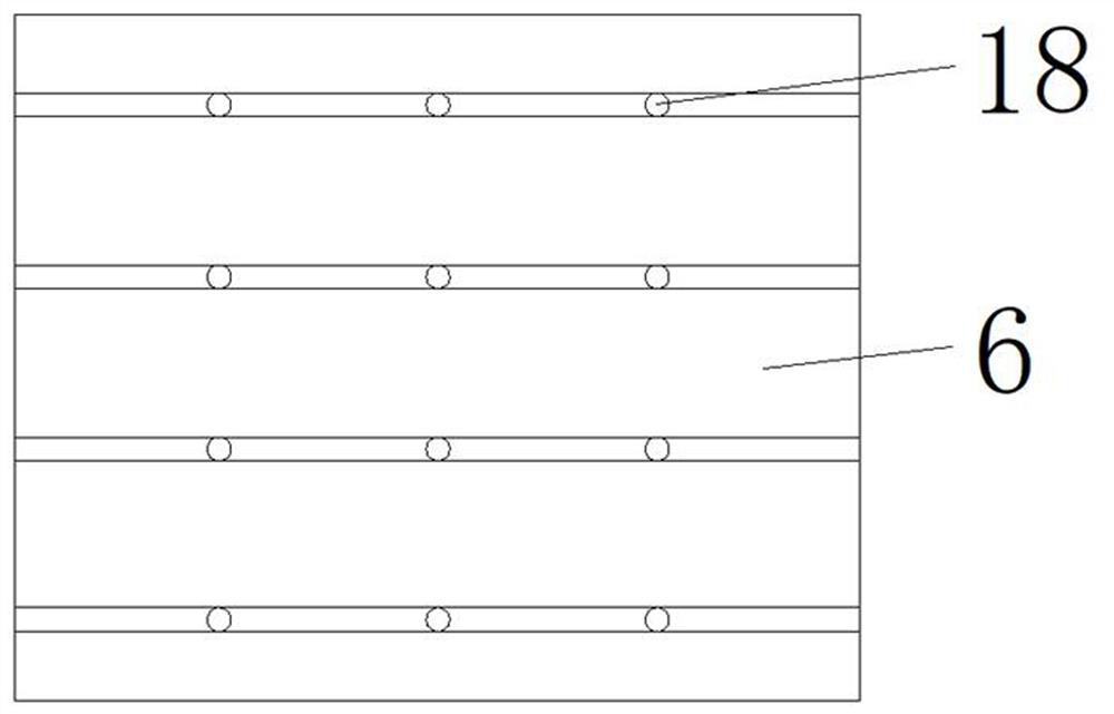
[0024] Such as Figure 1-3 A staged invisible airtight automatic road drainer shown includes a drainage cavity 3, the top of the drainage cavity 3 is provided with a water inlet groove 16 whose inner diameter is inclined from the outside to the inside, and the top of the drainage chamber 3 is covered with a water inlet groove 16. The matching cover body 6 has a water inlet 18 evenly opened on the cover body 6, and the bottom of the cover body 6 at the position of the water inlet 18 is connected with a water inlet pipe 5, and both sides of the bottom of the cover body 6 are fixed with support rods 2 for drainage. The inside of the cavity 3 is slidably connected with a sliding seat 4, and the inside of the sliding seat 4 is provided with a water storage tank 26, and the middle position on one side of the water storage tank 26 is provided with an overflow port 17, and the two sides of the bottom of the sliding seat 4 are fixed with mutually symmetrical The first rack 14, the top ...


PUM


Abstract

The invention discloses a staged invisible closed automatic road drainer, and belongs to the technical field of road drainage. The staged invisible closed automatic road drainer comprises a drainage cavity, the top of the drainage cavity is provided with a water inlet groove with the inner diameter inclined from outside to inside, the top of the drainage cavity is covered with a cover body matched with the water inlet groove, the cover body is uniformly provided with water inlets, a water inlet pipe is connected to the bottom, at the water inlet, of the cover body, a sliding seat is slidably connected to the interior of the drainage cavity, a water storage tank is formed in the sliding seat, and an overflow opening is formed in the middle of one side of the water storage tank. The gap between the cover body and the water inlet groove is automatically opened by increasing and reducing rainwater in the water storage tank, the water discharge amount is increased, water accumulation on the road is prevented, meanwhile, the sliding seat is driven to shake up and down through the increasing and reducing process of the rainwater in the water storage tank, the vibration effect is generated, silt falling onto the inclined face of the top of the sliding seat is vibrated, and silt conveying is accelerated.

Description

technical field [0001] The invention relates to the technical field of road drainage, in particular to a staged invisible airtight automatic road drain. Background technique [0002] In order to reduce water accumulation and water damage in highway engineering and eliminate water seepage in the pavement structure, it is necessary to set up a drainage system on the edge of the road, and the rainwater well is an important part of the system. However, there are many problems in the current highway drainage system. The first is the lack of drainage capacity. The area available for drainage per unit area is small. Due to the beautiful design of the road surface, there will not be too many rainwater wells, which limits drainage. When the amount of rainwater is heavy, there will be a lot of water on the road surface. When the high-speed cars pass by, the rain will splash, affect the vision, pollute the vehicles, easily cause traffic accidents, and threaten traffic safety. At the sa...

Claims


Application Information

Patent Timeline
Patent Type & Authority Applications(China)
IPC IPC(8): E03F5/04E03F5/10
CPCE03F5/0401E03F5/10Y02A30/60
Inventor 王彦章苏鹏王润平梁文辉赵志超秦小超李凤岭卫亚辉原英杰郭成成贾韵洁李艳明
Owner SHANXI TRAFFIC PLANNING PROSPECTING & DESIGN INST
Learn More