
Energy-saving and emission-reducing method applied to sintering flue gas SCR denitration and system thereof

A technology for sintering flue gas, energy saving and emission reduction, which is applied in the field of air pollution control and can solve environmental pollution and other problems

Inactive Publication Date: 2021-06-04
HUATIAN NANJING ENG & TECH CORP MCC +1
View PDF4 Cites 1 Cited by
  • Summary
  • Abstract
  • Description
  • Claims
  • Application Information

AI Technical Summary

Problems solved by technology

Although the heat exchanger is used for energy recovery and utilization in engineering to reduce energy consumption, it still needs to supplement the temperature difference of about 30°C through fuel combustion, and part of the fuel consumption accounts for about half of the operating cost of the denitrification system
The CO content in the sintering flue gas is generally 5000-10000ppm. As a toxic substance, CO is discharged directly without treatment, which will cause serious environmental pollution.

Method used


Image

  • Energy-saving and emission-reducing method applied to sintering flue gas SCR denitration and system thereof

Examples


Embodiment 1

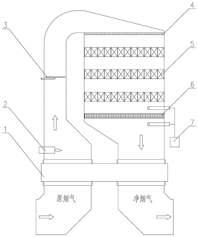
[0025] The flue gas temperature at the inlet of the denitrification system is 90°C, and the CO concentration is 5000ppm. After heat exchange in the heat exchanger 1, the temperature rises to 280°C. 3 After mixing, enter the SCR denitration catalyst bed layer 5 for denitration reaction, in which there is 2.5ppm unreacted NH 3 Enter the downstream CO catalytic combustion catalyst bed 6. Simultaneous CO catalytic combustion and NH on the CO catalytic combustion catalyst 3 Catalytic oxidation reaction, CO reduced from 5000ppm to 1000ppm, NH 3 From 2.5ppm to 0.5ppm, the flue gas temperature rises from 280°C to 310°C. Then the temperature of the clean flue gas is exchanged with the raw flue gas through a heat exchanger, and the temperature drops to 120°C before entering the downstream process.

Embodiment 2

[0027] The flue gas temperature at the inlet of the denitrification system is 80°C, and the CO concentration is 10,000ppm. After heat exchange in the heat exchanger, the temperature rises to 280°C. 3 After mixing, it enters the SCR denitrification catalyst bed for denitrification reaction, in which there is 3ppm unreacted NH 3 Enter the downstream CO catalytic combustion catalyst bed. Simultaneous CO catalytic combustion and NH on the CO catalytic combustion catalyst 3 Catalytic oxidation reaction, CO reduced from 10000ppm to 1500ppm, NH 3 From 3ppm to 0.6ppm, the flue gas temperature rises from 280°C to 330°C. Then the temperature of the clean flue gas is exchanged with the raw flue gas through a heat exchanger, and the temperature drops to 130°C before entering the downstream process.

[0028] To sum up, the present invention aims at energy saving and emission reduction. On the one hand, the catalytic combustion of CO can be used to generate heat, so as to greatly reduce ...


PUM


Abstract

The invention discloses an energy-saving and emission-reducing method applied to sintering flue gas SCR denitration and a system thereof. The method comprises the following steps: carrying out SCR reaction on sintering flue gas rthrough a denitration catalyst, entering a CO catalytic combustion catalyst bed layer, and enabling CO in the flue gas to be subjected to catalytic combustion reaction in the catalyst bed layer. According to the energy-saving and emission-reducing method applied to sintering flue gas SCR denitration and the system thereof, the sintering flue gas enters the CO catalytic combustion catalyst bed layer after being subjected to SCR denitration; after CO in the flue gas is subjected to catalytic combustion, the temperature of the flue gas can be increased by more than 30 DEG C; CO is reduced by more than 70%; meanwhile, the CO catalytic combustion catalyst and NH3 escaped from SCR denitration are subjected to catalytic oxidation reaction to generate harmless N2; ammonia escape can be reduced from 3ppm to 0.5ppm; high-temperature flue gas obtained after CO catalytic combustion enters a clean flue gas inlet of a heat exchanger and exchanges heat with low-temperature flue gas on the original flue gas side; the original flue gas obtained after exchanging heat can directly reach the temperature needed by denitration reaction; and additional heat supplement is not needed.

Description

technical field [0001] The invention is applicable to the technical field of air pollution control, and specifically relates to a method and system for SCR denitrification, energy saving and emission reduction of sintering flue gas. Background technique [0002] Under the circumstances that the prevention and control of air pollution in the thermal power industry has reached a certain level, non-electric industries such as iron and steel metallurgy and building materials have also quickly kicked off the prelude to standard upgrading and transformation. For the prevention and control of air pollution in non-electricity industries, the Ministry of Environmental Protection and local provincial and municipal governments have issued a series of more stringent ultra-low emission standards for pollutants. As a key emission source of air pollutants in the iron and steel industry, sintering flue gas is mainly characterized by large amount of flue gas and low temperature. At present,...

Claims


Application Information

Patent Timeline
IPC IPC(8): F27D17/00F23G7/07B01D53/86B01D53/56
CPCF27D17/008F27D17/004F23G7/07B01D53/8625F23G2209/14B01D2258/0283B01D2251/2062
Inventor 李启超安忠义范维义
Owner HUATIAN NANJING ENG & TECH CORP MCC
Learn More