
Medical heat pipe drill bit for cortical bone processing, and use method of medical heat pipe drill bit

A cortical bone and drill technology, used in bone drill guidance, medical science, surgery, etc., can solve the problems of high temperature in the cutting part of the tool, environmental pollution, human bone damage, etc.

Active Publication Date: 2021-06-08
NANJING FORESTRY UNIV
View PDF25 Cites 2 Cited by
  • Summary
  • Abstract
  • Description
  • Claims
  • Application Information

AI Technical Summary

Problems solved by technology

These methods can meet the needs of heat dissipation to some extent, but they cannot be applied to all cutting processes, and they all have their shortcomings.
As far as cooling with cutting fluid is poured, it not only causes a certain degree of pollution to the environment, but also may have a certain negative impact on the human body. Some cutting fluids cannot be reused, resulting in a high cost
In addition, in orthopedic surgery in clinical medicine, drills are used to process human bones, and the main problem that restricts the use of drills in clinical orthopedic surgery to process human bones is that a lot of heat generated during the process causes the tool to cut parts. the temperature is too high
If the temperature exceeds 47°C, it will cause different degrees of damage to human bones, which will affect the recovery of bones.

Method used


Image

  • Medical heat pipe drill bit for cortical bone processing, and use method of medical heat pipe drill bit
  • Medical heat pipe drill bit for cortical bone processing, and use method of medical heat pipe drill bit
  • Medical heat pipe drill bit for cortical bone processing, and use method of medical heat pipe drill bit

Examples


Embodiment Construction

[0034] Embodiments of the present invention will be further described in detail below in conjunction with the accompanying drawings.

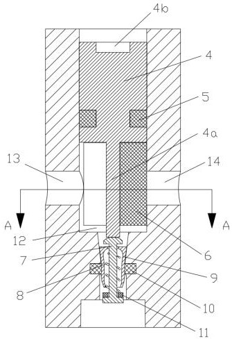
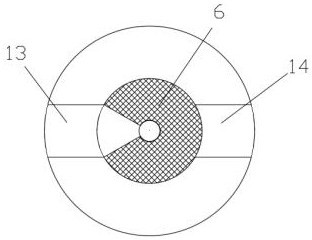
[0035] like Figure 1-2As shown, a medical heat pipe drill for cortical bone processing mainly includes: a drill section 1 , an airtight device 2 , and a heat pipe heat exchange section 3 . The heat exchange section 3 of the heat pipe is located at the root of the drill bit, the part near the front end of the drill bit is the evaporating section 3a of the heat pipe, the part near the top of the shank of the drill bit is the condensing section 3c of the heat pipe, and the part between the evaporating section 3a and the condensing section 3c is the evaporating section 3a of the heat pipe. Insulation section 3b. The rear end of the cortical bone processing drill bit is provided with an axial airtight device mounting hole 12, and the rear end of the cortical bone processing drill bit is also provided with a negative pressure air extraction hole 13...


PUM


Abstract

The invention discloses a medical heat pipe drill bit for cortical bone processing. The medical heat pipe drill bit for cortical bone processing comprises a cortical bone processing drill bit body; the cortical bone processing drill bit body comprises a drill bit section, an airtight device and a heat pipe heat exchange section; the drill bit section is located at the front end of the cortical bone processing drill bit body and used for drilling cortical bones; the front end of the heat pipe heat exchange section is connected with the rear end of the drill bit section; the rear end of the heat pipe heat exchange section is connected with the airtight device; the airtight device comprises a plug, a fan-shaped sealing ring, an ejector rod, a spring, a valve piece and an end face sealing ring; the fan-shaped sealing ring is fixedly installed on the plug; when the plug rotates, the fan-shaped sealing ring can seal a negative pressure air exhaust hole or a liquid injection hole or seal the negative pressure air exhaust hole and the liquid injection hole at the same time; and the plug can be pushed by external force to move forwards to push the ejector rod, so that the end face sealing ring moves forwards to remove sealing of the front end of the valve cavity. The problems of cell damage and operation failure caused by too high temperature in the cortical bone drilling process are solved; and the expected heat dissipation effect is achieved by designing the heat pipe structure in the drill bit.

Description

technical field [0001] The invention relates to the technical field of medical devices, in particular to a medical heat pipe drill bit for cortical bone processing and a use method thereof. Background technique [0002] With the development of science and technology and the advancement of the medical field, the demand for more perfect medical devices is generated. For medical machinery, a large amount of heat is likely to have a certain degree of adverse effects on the processed object during mechanical cutting and may have a negative effect on the service life of medical knives. Rapid heat dissipation of the heat, which will have a considerable positive impact on various cutting processes. [0003] In traditional cutting, the way to dissipate heat is mainly to take away heat through physical methods, such as using fans to cool down, using circulating liquid circuits to take away heat, and using cutting fluid to pour cooling. These methods can meet the needs of heat dissip...

Claims


Application Information

Patent Timeline
Patent Type & Authority Applications(China)
IPC IPC(8): A61B17/16A61B17/17
CPCA61B17/1615A61B17/17
Inventor 陈佳佳许海天王藤茂狄新宇周乐张文政
Owner NANJING FORESTRY UNIV
Learn More