Ceramic pump body

A ceramic pump, shaft body technology, applied in the direction of pumps, pump components, non-variable-capacity pumps, etc., can solve the problems of reducing fluid erosion on seal rings and seal ring grooves, poor anti-cavitation performance, and cavitation. Achieve high yield and dimensional accuracy, improve mechanical strength and prolong service life

Pending Publication Date: 2021-06-08
GUANGZHOU TOTALL MATERIAL TECH CO LTD
View PDF0 Cites 1 Cited by
  • Summary
  • Abstract
  • Description
  • Claims
  • Application Information

AI Technical Summary

Problems solved by technology

Slurry pumps made of these wear-resistant materials are difficult to meet the requirements of use under many working conditions. The main problems are as follows: 1) The problem of wear is prominent, and the life of the flow-passing parts often cannot meet the requirements of use; 2) The cavitation resistance is poor, This is because as the concentration of the two-phase flow increases, the fluidity of the medium continues to decrease, and the NPSH is much smaller than that of clean water, causing cavitation to occur when the flow rate of the pump is much lower than the calibrated value. Not only the flow parts are easily damaged, but the pump The performance such as efficiency, head, flow, etc. are significantly reduced
However, this structure also has obvious disadvantages. The medium will contact the metal material where the sealing ring is located and cause abrasion or corrosion to it, and make the seal invalid
Sealing rings or gaskets can also be placed on the part where the ceramic material is located, but the ceramic material will be deformed during the sintering process. The size of the pump body and pump cover still cannot guarantee the matching accuracy required by the seal. In order to achieve a reliable seal between the rear guard plate and the volute, and between the front guard plate and the volute, the front guard plate and the volute, the There is a small gap fit between the rear guard plate and the volute to reduce the fluid’s erosion of the sealing ring and the sealing ring groove. The existing technology can only reserve a margin before sintering for this purpose, and carry out mechanical cleaning after sintering. Machining to achieve a small clearance fit
Due to the extremely high hardness of ceramics, machining is extremely difficult, not only the efficiency is very low, but the cost is also high, which greatly limits its application range

Method used


Image

  • Ceramic pump body
  • Ceramic pump body
  • Ceramic pump body

Examples


Embodiment 1

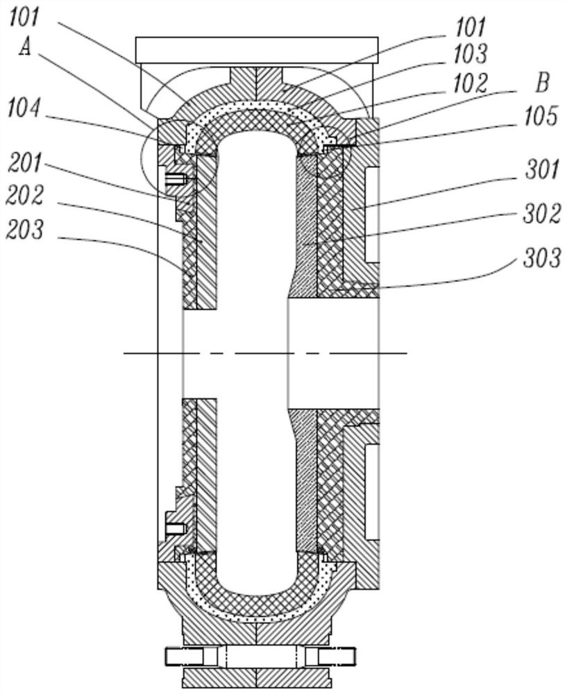
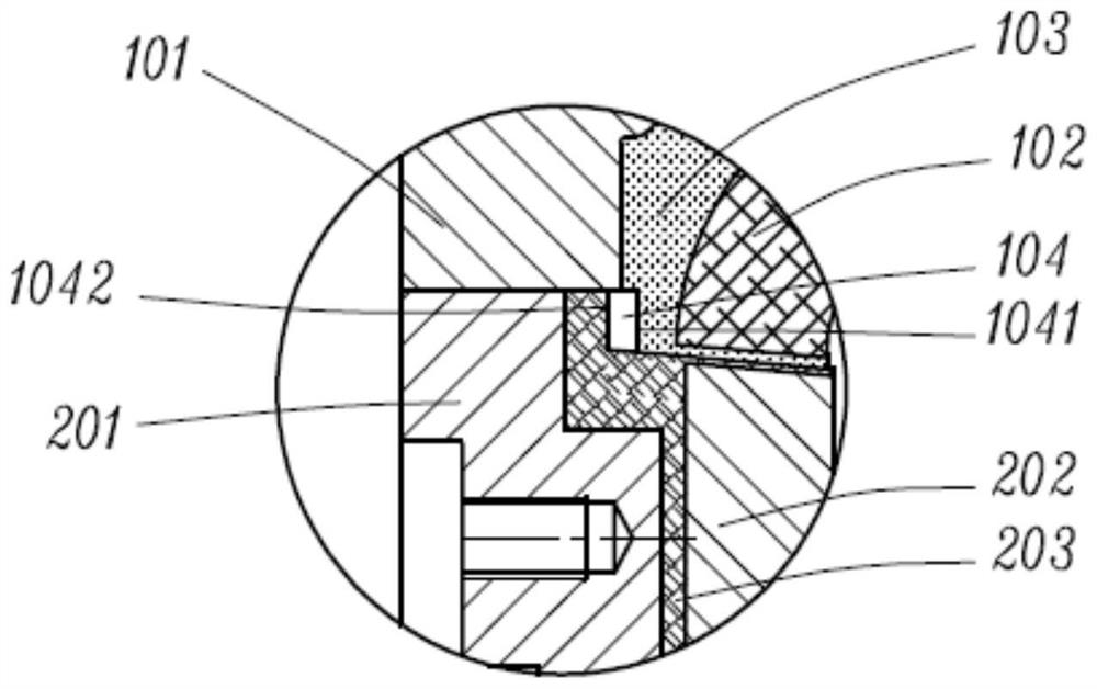
[0047] Specific embodiments of the present invention 1 refer to Figure 1-7 As shown, a ceramic pump body includes a volute and a guard plate, and the volute includes a casing 101 and a volute lining 102 . The guard plate includes a guard plate skeleton and a guard plate inner liner, and a first buffer layer 103 is arranged between the casing 101 and the volute inner liner 102 . The middle part of the volute is provided with a through hole and a tapered hole sequentially from the outside to the inside, and the through hole is connected with the tapered hole through the first axial end surface. A second buffer layer is arranged between the frame of the guard plate and the lining of the guard plate, a shaft body and a taper shaft are arranged on the guard plate in turn, and the shaft body is connected to the taper shaft through the second axial end face. The shaft fits with the through hole, and the taper shaft fits with the taper hole. An annular space for placing a seal is f...

Embodiment 2

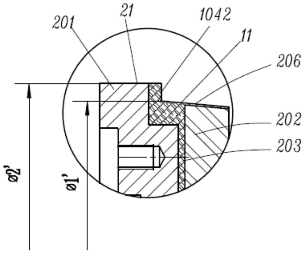
[0060] Such as Figure 8 , 9 , 10, this embodiment is roughly the same as Embodiment 1, the difference is that no front guard plate is provided, and the second axial rear end surface 1042 of the first annular space 104 is made of silicon carbide ceramic material, and the first tapered shaft The material of 11 is also silicon carbide ceramics. Obviously, the rear guard plate of this structure generally needs to be machined to meet the sealing requirements, but because the size of the rear guard plate is small and the outer circle of the machining shaft, the cost of this mechanical cutting process is relatively low, so It can still meet the requirements of some production processes.

Embodiment 3

[0062] Such as Figure 11 to Figure 14 As shown, this embodiment is substantially the same as Embodiment 2, except that the volute is provided with auxiliary through holes, and the auxiliary through holes, through holes and tapered holes are arranged in sequence. The auxiliary through hole is connected with the through hole through the first auxiliary axial end surface. An auxiliary shaft body is arranged on the guard plate, the auxiliary shaft body, the shaft body and the taper shaft are arranged in sequence, and the auxiliary shaft body is connected with the shaft body through the second auxiliary axial end surface. The inner wall of the auxiliary through hole, the outer wall of the shaft, the first auxiliary axial end surface and the second auxiliary axial end surface enclose an auxiliary annular space for placing the auxiliary seal.

[0063] In this embodiment, the auxiliary through hole is the first auxiliary through hole 50, which is arranged on the rear side of the vol...


PUM

PropertyMeasurementUnit
thicknessaaaaaaaaaa
thicknessaaaaaaaaaa
thicknessaaaaaaaaaa

Abstract

The invention discloses a ceramic pump body which comprises a volute and a protective plate, and the volute comprises a shell and a volute lining. The protective plate comprises a protective plate framework and a protective plate lining, and a first buffer layer is arranged between the shell and the volute lining. A through hole and a taper hole are sequentially formed in the middle of the volute from outside to inside, and the through hole is connected with the taper hole through a first axial end face. A second buffer layer is arranged between the protective plate framework and the protective plate lining, a shaft body and a conical shaft are sequentially arranged on the protective plate, and the shaft body is connected with the conical shaft through a second axial end face. The shaft body is matched with the through hole, and the conical shaft is matched with the taper hole. An annular space which is defined by the first axial end face, the second axial end face, the inner wall of the through hole and the outer wall of the conical shaft and used for containing a sealing piece is arranged between the volute and the protective plate. According to the provided ceramic pump body, a medium cannot be in contact with a metal piece of the volute or the protective plate, so that the ceramic pump body not only has better wear resistance and corrosion resistance, but also can control the manufacturing cost within a proper range.

Description

technical field [0001] The invention relates to the field of rotary power pump equipment, in particular to a ceramic pump body. Background technique [0002] In industries such as mineral processing and smelting, centrifugal pumps are often used to transport some abrasive solid-liquid two-phase flows, and slurry pumps are often used. Common slurry pumps are usually made of wear-resistant alloys such as Cr26 and Cr15Mo3. Slurry pumps made of these wear-resistant materials are difficult to meet the requirements of use under many working conditions. The main problems are as follows: 1) The problem of wear is prominent, and the life of the flow-passing parts often cannot meet the requirements of use; 2) The cavitation resistance is poor, This is because as the concentration of the two-phase flow increases, the fluidity of the medium continues to decrease, and the NPSH is much smaller than that of clean water, causing cavitation to occur when the flow rate of the pump is much lo...

Claims


Application Information

Patent Timeline
Patent Type & Authority Applications(China)
IPC IPC(8): F04D29/42F04D29/02
CPCF04D29/026F04D29/426F04D29/4266F04D29/4286F05D2300/2261F04D29/02F04D29/08F04D29/42
Inventor 肖琼王学东
Owner GUANGZHOU TOTALL MATERIAL TECH CO LTD
Why Eureka
Try Eureka