
Double-sided heating steam generator with spiral tooth-shaped structures

A steam generator and double-sided heating technology, applied in steam generation, steam generation methods, steam boilers, etc., can solve the problems of poor water dispersion, high cost, affecting heating efficiency and heat utilization efficiency, etc.

Pending Publication Date: 2021-06-08
杭州佐帕斯工业有限公司
View PDF0 Cites 0 Cited by
  • Summary
  • Abstract
  • Description
  • Claims
  • Application Information

AI Technical Summary

Problems solved by technology

The coil structure is in a series relationship, the temperature difference between front and back is large, and the thermal efficiency is low; the column cylindrical type has complicated process and high cost; the labyrinth channel type has poor water distribution capacity, which affects the heating efficiency and heat utilization efficiency; There are connected channels between the boiling water channels. During the inversion process of the steam generator, it is easy to cause only part of the water to vaporize, and the steam port ejects hot steam and hot water at the same time. The humidity of the steam is high.

Method used


Image

  • Double-sided heating steam generator with spiral tooth-shaped structures
  • Double-sided heating steam generator with spiral tooth-shaped structures
  • Double-sided heating steam generator with spiral tooth-shaped structures

Examples


Embodiment 1

[0025] Below in conjunction with accompanying drawing and specific embodiment the present invention is described in further detail:

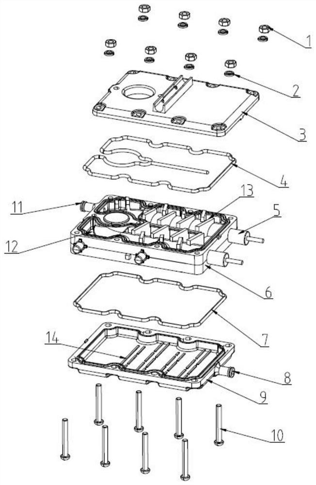
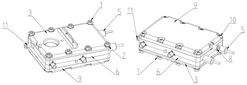
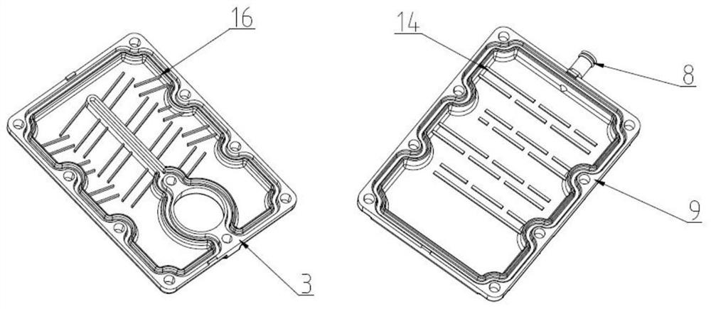
[0026] Such as Figure 1-5 As shown, a double-sided heating steam generator with a spiral tooth structure includes a heating element 6, and a heating tube 5 is die-cast in the heating element 6, such as image 3 As shown, the upper and lower ends of the heating element 6 are fastened with an upper cover 3 and a lower cover 9 respectively, forming airtight cavities at the upper and lower ends of the heating element 6 respectively. The heating element 6 and the upper and lower covers 9 are assembled and fixed by locking screws 10, nuts 1 and spring washers 2. Silicone sealing rings 4, 7 for sealing are also provided between the heating element 6 and the upper and lower covers 3, 9.

[0027] The upper end surface of the heating element 6 is provided with a plurality of helical tooth-shaped structures 13 along the axial direction of the heating tub...


PUM


Abstract

The invention belongs to the technical field of steam household appliances, and particularly relates to a double-sided heating steam generator with spiral tooth-shaped structures. The steam generator comprises a heating body, wherein heating pipes are arranged in the heating body in a pressure casting mode, and an upper cover and a lower cover are buckled to the upper end face and the lower end face of the heating body respectively; the multiple spiral tooth-shaped structures are arranged on the upper end face of the heating body in the axial direction of the heating pipes, every two adjacent spiral tooth-shaped structures form a splayed liquid flow channel, a water inlet is formed in the side portion of the left end of the upper end face of the heating body, and the water inlet communicates with the liquid flow channels; a steam outlet is formed in the right side end of the lower cover and communicates with a gas flow channel on the lower end face of the heating body; and steam connecting holes are formed in the positions, at the tail ends of the liquid flow channels, of the heating body in the vertical direction. By adopting the spiral tooth-shaped double-sided heating structure, the heat exchange area and the water dispersing capacity are greatly increased; and the spiral tooth-shaped structures play a role in blocking water, so that water flow is uniform, the uniformity of contact between the water and the heating body is improved, the steam discharging time is shortened, and the heat exchange efficiency is improved.

Description

technical field [0001] The invention belongs to the technical field of steam appliances, in particular to a double-sided heating steam generator with a spiral tooth structure. Background technique [0002] The high-temperature steam generated by the steam mop has super degreasing and sterilizing functions. For difficult to deal with kitchen fumes, bathroom floors with bacterial growth, or car engines and interiors, etc., the steam mop can be used without any detergent. Quickly and effectively removes stains and bacteria. The existing steam structure is divided into coil structure, three-dimensional cylinder type, labyrinth groove flow channel type, and double-sided heating and boiling water type. The coil structure is in a series relationship, the temperature difference between front and back is large, and the thermal efficiency is low; the column column type has complicated process and high cost; There are connected passages between the boiling water passages. During the ...

Claims


Application Information

Patent Timeline
IPC IPC(8): F22B1/28F22B37/02F22B37/12
CPCF22B1/28F22B37/02F22B37/12
Inventor 何业洪吕希健颜慧敏
Owner 杭州佐帕斯工业有限公司
Learn More