
Distributed phased matrix system

A distributed, phased array antenna technology, applied in diversity/multi-antenna systems, antenna arrays, space transmit diversity, etc., can solve the problem of high cost of parabolic antennas

Pending Publication Date: 2021-06-08
北京北木波谱科技有限公司
View PDF6 Cites 0 Cited by
  • Summary
  • Abstract
  • Description
  • Claims
  • Application Information

AI Technical Summary

Problems solved by technology

[0003] The main purpose of this application is to provide a distributed phased matrix system to solve the problem of high cost of parabolic antennas

Method used


Image

  • Distributed phased matrix system
  • Distributed phased matrix system
  • Distributed phased matrix system

Examples


Embodiment Construction

[0039] In order to enable those skilled in the art to better understand the solution of the present application, the technical solution in the embodiment of the application will be clearly and completely described below in conjunction with the accompanying drawings in the embodiment of the application. Obviously, the described embodiment is only It is an embodiment of a part of the application, but not all of the embodiments. Based on the embodiments in this application, all other embodiments obtained by persons of ordinary skill in the art without creative efforts shall fall within the scope of protection of this application.

[0040] It should be noted that, in the case of no conflict, the embodiments in the present application and the features in the embodiments can be combined with each other. The present application will be described in detail below with reference to the accompanying drawings and embodiments.

[0041] This application proposes a distributed phase control...


PUM


Abstract

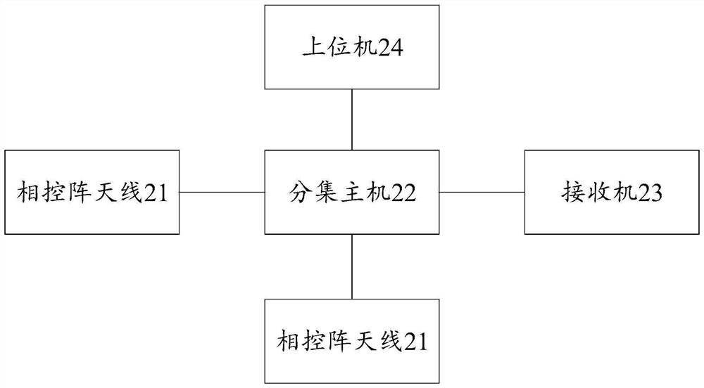
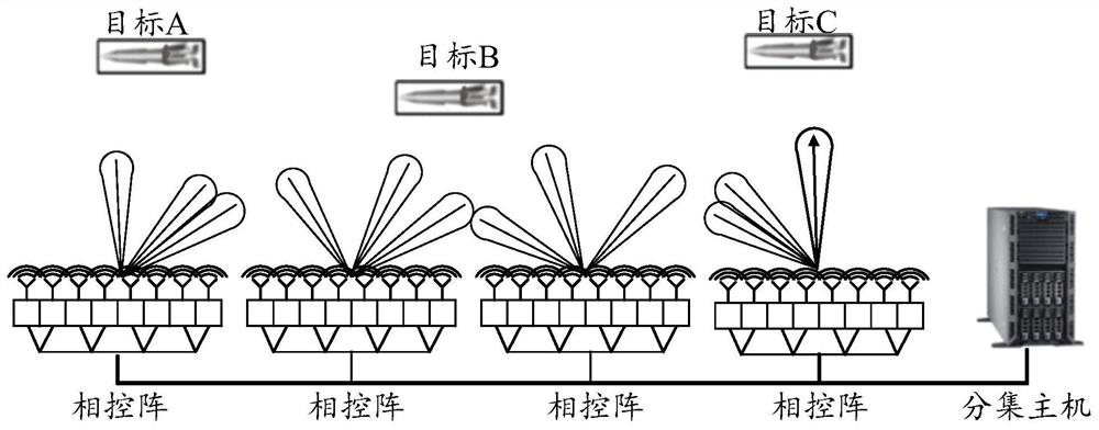
The invention discloses a distributed phased matrix system which comprises a diversity host and a plurality of phased array antennas electrically connected with the diversity host, wherein each phased array antenna is used for monitoring a target, generating an output signal and sending the output signal to the diversity host; and the diversity host is used for receiving the output signal sent by each phased array antenna, synthesizing the received output signal sent by each phased array antenna to obtain a synthesized signal and outputting the synthesized signal. The distributed phased array provided by the invention not only obtains the characteristics of high directionality, high gain and flexible tracking of a phased array antenna array, but also has the effects of space diversity and multipath effect resistance. Multiple targets can be tracked at the same time only through one set of antenna, and compared with a parabolic antenna, the complexity and cost of the system are remarkably reduced.

Description

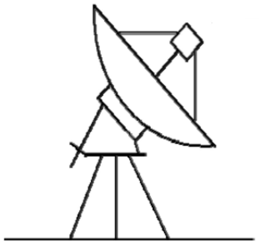
technical field [0001] The present application relates to the technical field of antennas, and in particular, to a distributed phased matrix system. Background technique [0002] Traditional telemetry receiving stations use parabolic antennas to track targets and receive signals, see attached figure 1 A conventional parabolic antenna is shown. The parabolic antenna only supports signal reception of a single target, is bulky, difficult to maintain, and poor in mobility. When monitoring targets in the sky, such as missiles and aircraft, the paraboloid needs to rotate with the target in the sky to achieve Continuous monitoring, so a successful and expensive mechanical electrical servo system is required to drive the motion of the parabola. Moreover, a set of parabolic antennas in the prior art can only monitor one target in the sky, but cannot monitor multiple targets. When there are multiple targets in the sky, multiple parabolic antennas are required, which is costly and m...

Claims


Application Information

Patent Timeline
Patent Type & Authority Applications(China)
IPC IPC(8): H01Q1/24H01Q21/00H04B7/08
CPCH01Q1/24H01Q21/00H04B7/08
Inventor 刘胤廷
Owner 北京北木波谱科技有限公司
Learn More